
Method for determining reasonable well bottom pressure subjected to constant pressure injection by polymer injection well

A bottomhole pressure and determination method technology, which is applied in wellbore/well components, earthwork drilling, electrical digital data processing, etc., can solve the problem that the slope of the Hall curve does not rise significantly, and the injection pressure of the polymer injection well rises too fast, which is uneconomical. Improve the recovery rate and other issues to achieve the effect of increasing the recovery rate, deepening the funnel range, and easy application

Active Publication Date: 2020-11-13
CNOOC TIANJIN BRANCH +1
View PDF7 Cites 1 Cited by
  • Summary
  • Abstract
  • Description
  • Claims
  • Application Information

AI Technical Summary

Problems solved by technology

If the pressure setting is too high, the injection pressure of the polymer injection well will rise too fast, the injection volume will not meet the injection requirements, or even exceed the formation fracture pressure; if the pressure setting is too low, the slope of the Hall curve will not rise significantly, and it will not be possible to economically EOR

Method used


Image

  • Method for determining reasonable well bottom pressure subjected to constant pressure injection by polymer injection well
  • Method for determining reasonable well bottom pressure subjected to constant pressure injection by polymer injection well
  • Method for determining reasonable well bottom pressure subjected to constant pressure injection by polymer injection well

Examples


Embodiment Construction

[0030] The following will clearly and completely describe the technical solutions in the embodiments of the present invention with reference to the accompanying drawings in the embodiments of the present invention. Obviously, the described embodiments are only some of the embodiments of the present invention, not all of them. Based on the embodiments of the present invention, all other embodiments obtained by persons of ordinary skill in the art without making creative efforts belong to the protection scope of the present invention.

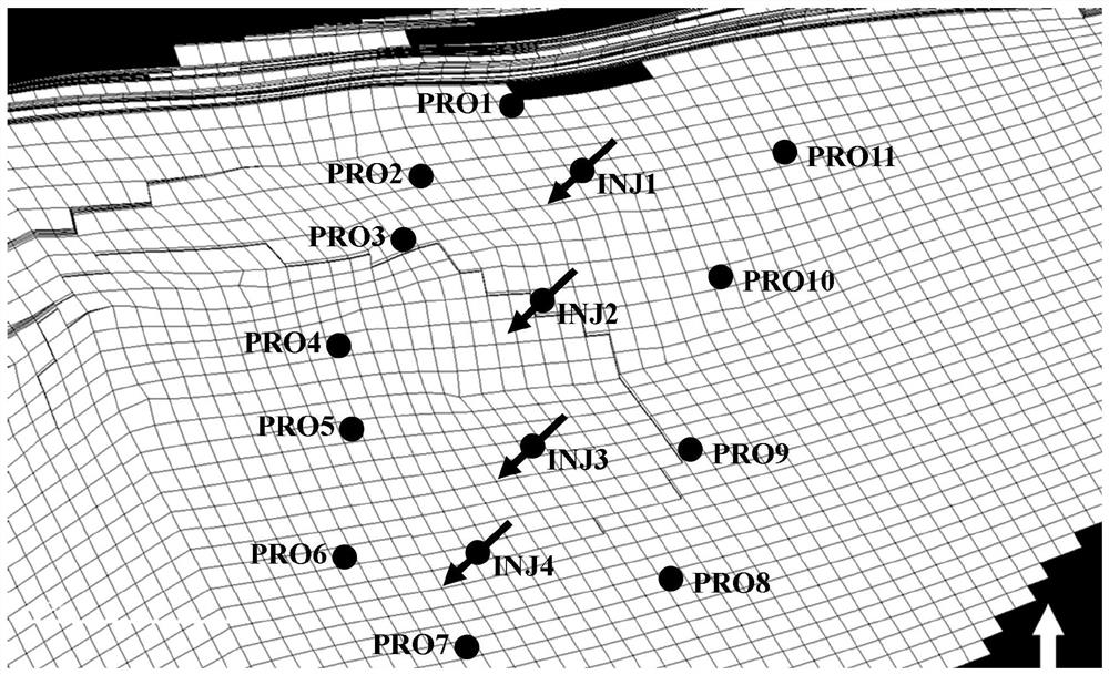
[0031] In this embodiment, taking a constant-pressure polymer injection well group in Bohai J Oilfield as an example, the method of the present invention is used to calculate the reasonable injection bottomhole pressure of 4 polymer injection wells. Such as figure 1 As shown, INJ1-INJ4 in the injection-production well group well positions of this embodiment are polymer injection wells, and PRO1-PRO11 are production wells, and the specific steps a...


PUM

PropertyMeasurementUnit
Permeabilityaaaaaaaaaa

Abstract

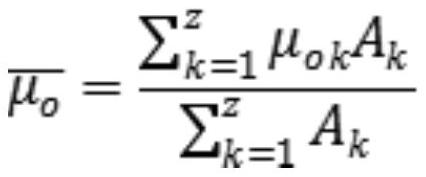
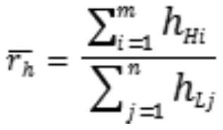
The invention relates to a method for determining reasonable well bottom pressure subjected to constant pressure injection by a polymer injection well. The method comprises the following steps of: 1)collecting a constant pressure injection parameter of a target polymer flooding well group, and according to field dynamic sampling, determining the practical injection polymer viscosity of the polymer injection well; 2) establishing a three-dimensional geologic model in a control area of the well group to obtain the rock fluid parameter of each grid in the control area, through grid area weighting, obtaining the average stratum crude oil viscosity of the well group, and carrying out statics on the thickness of each highly permeable layer and each low permeable layer in the control area to obtain an average thickness ratio; 3) determining a reasonable injection well bottom pressure multiple; and 4) on the basis of the three-dimensional geologic model, carrying out numerical value simulation operation, obtaining stable injection well bottom pressure of the polymer injection well under a constant speed polymer driving condition, and further determining the reasonable injection well bottom pressure. The method is convenient to apply, is high in maneuverability, and can provide effective guidance for formulating a polymer flooding "one well with one pressure" refined regulation and control strategy and further improving a recovery ratio.

Description

technical field [0001] The invention belongs to the field of oilfield development, and in particular relates to a method for determining a reasonable well bottom pressure for constant pressure injection in a polymer injection well. Background technique [0002] With the rapid development of the economy, my country's demand for oil resources is increasing day by day. For complex reservoirs such as heavy oil reservoirs, the degree of recovery under conventional water flooding conditions is limited, and it is urgent to use new methods to enhance recovery in the late stage of oilfield development. At present, the chemical flooding EOR technology based on polymer flooding has become the basis and key to the efficient development of domestic oilfields, and plays an important role in achieving the goal of increasing reserves and production by three barrels of oil. For reservoir development, "pressure is the soul", and the increase in injection pressure is the most important dynami...

Claims


Application Information

Patent Timeline
IPC IPC(8): E21B43/22E21B49/00E21B47/00G06F30/20G06F119/14
CPCE21B43/16E21B49/00E21B47/00G06F30/20G06F2119/14
Inventor 杨晗旭张健康晓东未志杰曾杨王旭东刘玉洋
Owner CNOOC TIANJIN BRANCH
Learn More