Non-contact ultra-wideband waveguide rotary joint, control system, method and application

A rotary joint and non-contact technology, which is applied in the direction of waveguide devices, antenna grounding switch structure connection, electrical components, etc., can solve the problem of affecting the standing wave and insertion loss performance of rotary joints, the wear and tear of contact rotary joints, and the inability to achieve broadband Performance and other issues, achieve good electromagnetic transmission performance, avoid wear problems, and ensure the effect of broadband electromagnetic shielding

Active Publication Date: 2020-11-13
XIDIAN UNIV
View PDF5 Cites 6 Cited by
  • Summary
  • Abstract
  • Description
  • Claims
  • Application Information

AI Technical Summary

Problems solved by technology

[0007]Contact rotary joints have problems of wear and unstable rotation, while direct non-contact structures will cause electromagnetic leakage, which will seriously affect the standing wave and insertion loss of rotary joints Performance, although the non-contact structure using the choke groove structure avoids contact, but the choke groove relies on a quarter-wavelength conversion structure, which is a narrow-band structure and cannot achieve broadband performance

Method used


Image

  • Non-contact ultra-wideband waveguide rotary joint, control system, method and application
  • Non-contact ultra-wideband waveguide rotary joint, control system, method and application
  • Non-contact ultra-wideband waveguide rotary joint, control system, method and application

Examples


Embodiment Construction

[0051] In order to make the object, technical solution and advantages of the present invention more clear, the present invention will be further described in detail below in conjunction with the examples. It should be understood that the specific embodiments described here are only used to explain the present invention, not to limit the present invention.

[0052] Aiming at the problems existing in the prior art, the present invention provides an L-shaped non-contact ultra-broadband waveguide rotary joint, control system, method and application. The present invention will be described in detail below with reference to the accompanying drawings.

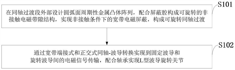
[0053] Such as figure 1 As shown, the control method of the L-type non-contact ultra-broadband waveguide rotary joint provided by the present invention includes the following steps:

[0054] S101: Design a circular-arc surface periodic metal convex array outside the coaxial transition section, cooperate with the shielding cavity to f...


PUM


Abstract

The invention belongs to the technical field of communication and radar antenna system components. The invention discloses a non-contact ultra wide band waveguide rotary joint, a control system, a control method and application, an arc surface periodic metal convex body array is designed outside a coaxial transition section, a rotatable non-contact electromagnetic band gap structure is formed by matching with a shielding cavity, broadband electromagnetic shielding is realized under a proper size, and non-contact rotatable coaxial transition is formed; electromagnetic signal transmission between the fixed waveguide and the rotary waveguide is achieved through broadband terminating type and orthogonal type coaxial-waveguide conversion, and the L-shaped waveguide rotary joint is achieved in cooperation with a bearing. According to the invention, a rotatable broadband non-contact electromagnetic band gap structure is constructed at the rotating part, so that good electromagnetic transmission performance of the rotating joint is ensured, the working bandwidth can completely cover the corresponding waveguide main mode bandwidth, and the non-contact structure avoids structural wear of therotating part, so that rotation is more stable, and the service life is longer; and the joint can be widely applied to various communication, radar and antenna feed systems.

Description

technical field [0001] The invention belongs to the technical field of communication and radar antenna system components, and in particular relates to a non-contact ultra-broadband waveguide rotary joint, a control system, a method and an application. Background technique [0002] Today, rotary joints are important components in communication and radar antenna systems. In order to realize the continuous search, tracking and measurement of the target, it is usually required that the radiation mechanism of the antenna can realize 360° continuous rotation, and at the same time, it is necessary to ensure the uninterrupted transmission of electromagnetic signals during the rotation process. Therefore, a rotary joint must be used in the antenna feed system. In order to ensure that the microwave signal can be continuously and effectively transmitted during the rotation of the antenna. [0003] Currently, rotary joints include waveguide rotary joints and coaxial rotary joints. The...

Claims


Application Information

Patent Timeline
Patent Type & Authority Applications(China)
IPC IPC(8): H01P1/06H01Q1/50
CPCH01P1/067H01Q1/50
Inventor 孙冬全陈翔郭立新魏兵
Owner XIDIAN UNIV
Why Eureka
Try Eureka