Learning dataset creation method and device

A data set and guided configuration technology, applied in machine learning, image data processing, character and pattern recognition, etc., can solve problems such as inability to hide

Pending Publication Date: 2020-11-13
NARA INSTITUTE OF SCIENCE AND TECHNOLOGY
View PDF3 Cites 0 Cited by
  • Summary
  • Abstract
  • Description
  • Claims
  • Application Information

AI Technical Summary

Problems solved by technology

[0017] However, there is a problem that concealment cannot be performed u

Method used


Image

  • Learning dataset creation method and device
  • Learning dataset creation method and device
  • Learning dataset creation method and device

Examples


Embodiment 1

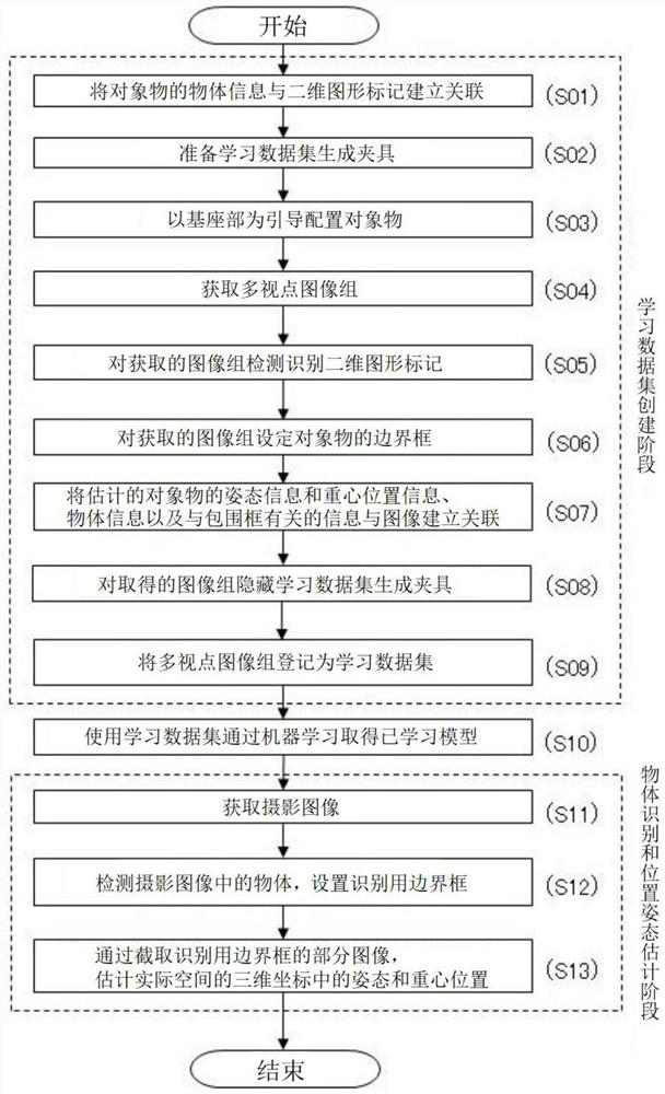
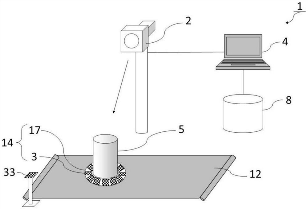
[0115] figure 1 A schematic flow of the process of creating a learning data set and a schematic flow of the process of object recognition and position and posture estimation are shown. Such as figure 1 As shown, in the stage of creating a learning data set, first, an AR marker (two-dimensional graphic marker) is used as a visual marker, and the object information of the object is associated with the AR marker (step S01). Next, prepare a jig for generating a learning data set marked with the associated two-dimensional graphics (step S02). The area of ​​the jig for generating the learning data set is used as a guide placement object (step S03). In the state where the object is arranged, a multi-viewpoint image group of the object is acquired (step S04 ). A two-dimensional graphic mark is detected and recognized on the acquired image group (step S05). A bounding box enclosing the entire object is set to the acquired image group (step S06). Associating the estimated pose info...

Embodiment 2

[0201] Figure 19 A schematic diagram of an image used to create the learning data set of the second embodiment is shown. Such as Figure 19 As shown in FIG. 7 , the conveyor belt 12 , objects ( 5 a to 5 c ), and bounding boxes ( 6 d to 6 f ) are displayed in the image 7 a.

[0202] In this embodiment, a three-dimensional bounding box ( 6d - 6f ) is set, which can be realized by setting a plurality of AR markers 3 .

[0203] That is, in this embodiment, the learning data set is created using the boards (14a-14c), but as Figure 7 As shown, taking the center point P of the circular plate 14a 1 as the origin, such as Figure 5 As shown, the object 5 is arranged using the position adjustment guide 18a or the like so that the center of the bottom of the object becomes the origin.

[0204] The height, shape, width, and depth of the object 5 are stored as object information data in advance as object attribute information. figure 1 shown in the database 8. can be obtained from...

Embodiment 3

[0206] Figure 20 It is a plan view of the learning data set generation jig in Example 3, and the number of displayed AR markers is (1) 8 and (2) 3. Such as Figure 20 As shown in (1), eight AR marks (3a to 3h) are provided on the circular base portion 17 of the plate 140a. Additionally, if Figure 20As shown in (2), three AR marks (3a to 3c) are provided on the circular base portion 17 of the plate 140b.

[0207] Here, it is not necessary to set 12 AR markers (3a-3l) like the boards (14a-14c) of Embodiment 1, and a smaller number can be set in consideration of the type, shape, manufacturing cost, etc. of the object 5. The structure of the AR marker. However, when capturing an image, it is preferable to capture two or more AR markers. This is because, as described above, by capturing two or more AR markers, it is possible to improve the recognition accuracy of the object, and it is also possible to set a three-dimensional bounding box.


PUM


Abstract

Provided are a method and a device that can efficiently create a learning dataset, which is used for machine learning and targets a plurality of objects. Object information is associated with a visualmarker, a learning dataset generation jig that is configured from a base part and a marker is used, said base part being provided with an area that serves as a guide for positioning a target object and said marker being fixed on the base part, the target object is positioned using the area as a guide and in this condition an image group of the entire object including the marker is acquired, the object information that was associated with the visual marker is acquired from the acquired image group, a reconfigured image group is generated from this image group by performing a concealment process on a region corresponding to the visual marker or the learning dataset generation jig, a bounding box is set in the reconfigured image group on the basis of the acquired object information, information relating to the bounding box, the object information, and estimated target object position information and location information are associated with a captured image, and a learning dataset for performing object recognition and location/position estimation for the target object is generated.

Description

technical field [0001] The invention relates to an automatic method for generating learning data sets in object recognition and position and attitude estimation based on machine learning. Background technique [0002] Conventionally, a robot equipped with artificial intelligence (Artificial Intelligence, hereinafter referred to as "AI") has been used as an automation measure for operations in factories and the like. In recent years, with the development of machine learning and deep learning (deep learning), in production systems such as factories, the development of AI using machine learning, etc., is rapidly progressing as a measure to realize the complete automation of factories. [0003] There is a demand for robot work automation in all industries, among which the food industry and logistics industry are expected areas for future development, and there is a great demand for robot work automation. [0004] However, since many products handled in the food industry or logi...

Claims


Application Information

Patent Timeline
IPC IPC(8): G06T7/00G06T7/13G06T7/70B25J13/08G06N20/00G06V10/764G06V10/774
CPCB25J13/08G06T7/74G06T2207/20204G06V20/64G06V20/20G06V10/242G06V10/245G06V10/82G06V10/764G06V10/774G06F18/2413G06T7/70
Inventor 友近圭汰清川拓哉小笠原司高松淳丁明
Owner NARA INSTITUTE OF SCIENCE AND TECHNOLOGY
Why Eureka
Try Eureka