
Automatic dredging device and vacuum pump for oil outlet of vacuum pump

A vacuum pump and vacuum pump technology, applied in the direction of pumps, engine components, engine seals, etc., can solve problems such as blockage of the circulating oil outlet, and achieve the effects of reducing flow resistance, facilitating installation, and improving quality

Active Publication Date: 2022-02-11
JA XINGTAI SOLAR CO LTD
View PDF13 Cites 0 Cited by
  • Summary
  • Abstract
  • Description
  • Claims
  • Application Information

AI Technical Summary

Problems solved by technology

[0003] In view of the above analysis, this application aims to provide an automatic dredging device for the oil outlet of a vacuum pump and a vacuum pump to solve the problem in the prior art that the grease of the vacuum pump is doped with foreign matter and the circulation oil outlet is blocked

Method used


Image

  • Automatic dredging device and vacuum pump for oil outlet of vacuum pump
  • Automatic dredging device and vacuum pump for oil outlet of vacuum pump
  • Automatic dredging device and vacuum pump for oil outlet of vacuum pump

Examples


Embodiment 1

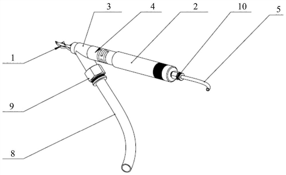
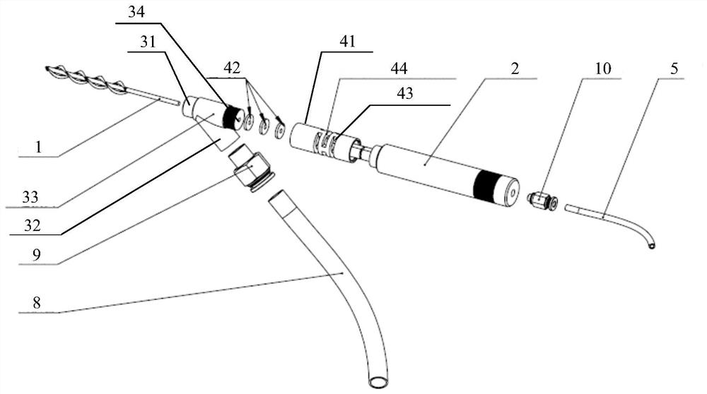
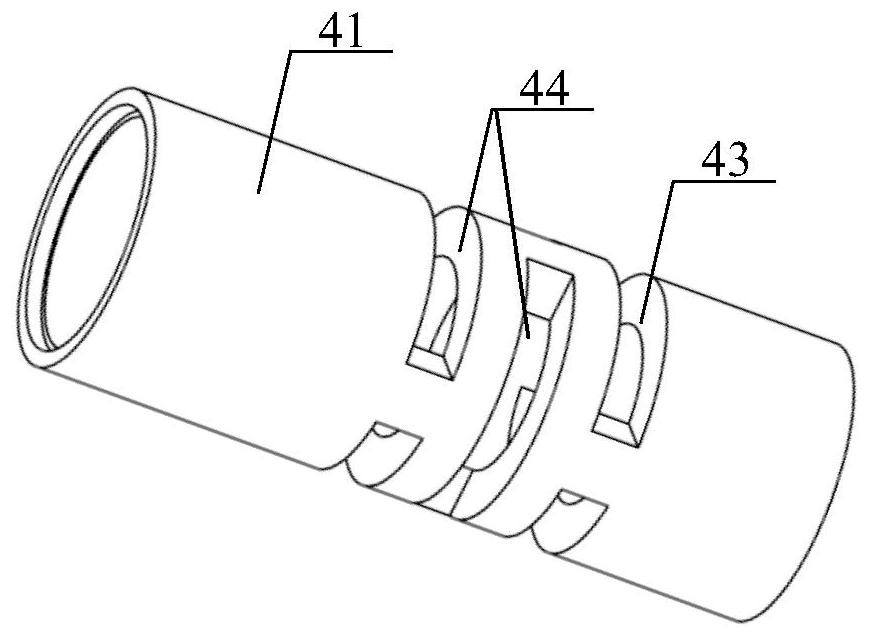
[0050] This embodiment provides an automatic dredging device for the oil outlet of a vacuum pump, see Figure 1 to Figure 5, including a stirring rod 1 and a motor 2 (for example, an air motor) that drives the stirring rod 1 to rotate, the stirring rod 1 is used to crush the solid impurities in the oil outlet, and one end of the stirring rod 1 extends through the vacuum pump oil outlet to the vacuum pump In the pump body, the other end is connected to the output end of the motor 2, and the motor 2 is used to provide rotational power for the stirring rod 1.

[0051] During implementation, turn on the motor 2, the output end of the motor 2 rotates, and then drives the stirring rod 1 to rotate, and the rotating stirring rod 1 crushes the solid impurities in the connection between the vacuum pump oil outlet and the vacuum pump body and the vacuum pump oil outlet and then discharges them.

[0052] Compared with the prior art, the automatic dredging device for the oil outlet of the ...

Embodiment 2

[0073] This embodiment provides a vacuum pump, see Figure 6 , which includes a vacuum pump body 7, a vacuum pump oil outlet 6 connected to the vacuum pump body 7, and an automatic dredging device located at the vacuum pump oil outlet 6. The automatic dredging device is used for the vacuum pump oil outlet provided by Embodiment 1 automatic dredging device.

[0074] Exemplarily, the above-mentioned vacuum pump is an oil-sealed vacuum pump, for example, a stationary vane vacuum pump, a rotary vane vacuum pump, a slide valve vacuum pump or a trochoidal vacuum pump.

[0075] In order to promote the disturbance of the oil in the oil outlet 6 of the vacuum pump and increase the contact probability of solid impurities with the stirring rod 1, the inner wall of the oil outlet 6 of the vacuum pump is set in a spiral structure, and the oil flows in the spiral oil outlet, and the disturbance itself is relatively small. Large, so that the probability of contact between the solid impuriti...


PUM


Abstract

The application discloses an automatic dredging device for the oil outlet of a vacuum pump and a vacuum pump, which belong to the technical field of photovoltaic automatic production, and are used to solve the problem in the prior art that the oil outlet of the vacuum pump is doped with foreign matter to cause blockage of the circulating oil outlet. The automatic dredging device of the present application includes a stirring rod, a motor that drives the stirring rod to rotate, and a motor power source that provides power for the motor. One end of the stirring rod extends through the oil outlet of the vacuum pump to the pump body of the vacuum pump, and the other end is connected to the output end of the motor. . The vacuum pump of the present application includes a vacuum pump body, a vacuum pump oil outlet connected to the vacuum pump body, and an automatic dredging device arranged at the vacuum pump oil outlet, and the automatic dredging device is the above-mentioned automatic dredging device. The automatic dredging device of the present application can be used to dredge the oil outlet of the vacuum pump.

Description

technical field [0001] The application belongs to the technical field of photovoltaic automatic production, and in particular relates to an automatic dredging device for an oil outlet of a vacuum pump and a vacuum pump. Background technique [0002] The existing photovoltaic laminator needs to use a vacuum pump for vacuuming. The EVA in the cavity of the photovoltaic laminator is melted and gasified, and after entering the pump body, it cools and solidifies, which will be mixed in the grease, causing the oil outlet of the vacuum pump to be blocked and the grease filter device to fail. , and then lead to abnormal occurrence of the vacuum pump. Contents of the invention [0003] In view of the above analysis, the present application aims to provide an automatic dredging device for the oil outlet of the vacuum pump and a vacuum pump to solve the problem in the prior art that the oil outlet of the vacuum pump is doped with foreign matter and the circulating oil outlet is block...

Claims


Application Information

Patent Timeline
Patent Type & Authority Patents(China)
IPC IPC(8): B08B9/051F04B37/14F16J15/10
CPCB08B9/051F04B37/14F16J15/102
Inventor 晋世森尹建仓李志远
Owner JA XINGTAI SOLAR CO LTD
Learn More