
Automatic fixed-length rope cutter

An automatic length-fixing and rope cutter technology, which is applied in the field of rope cutters, can solve the problems of low cutting efficiency and achieve the effects of high cutting efficiency, improving segment efficiency and changing cutting length.

Active Publication Date: 2020-11-17
安徽省乐悠悠户外用品有限公司
View PDF15 Cites 0 Cited by
  • Summary
  • Abstract
  • Description
  • Claims
  • Application Information

AI Technical Summary

Problems solved by technology

The ropes we use in our life are all segmented. In the process of segmenting the rope, there is an existing problem of segmenting by manual cutting, and the efficiency of cutting and segmenting is low.

Method used


Image

  • Automatic fixed-length rope cutter
  • Automatic fixed-length rope cutter
  • Automatic fixed-length rope cutter

Examples


Embodiment 1

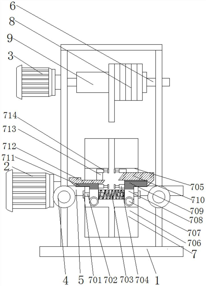
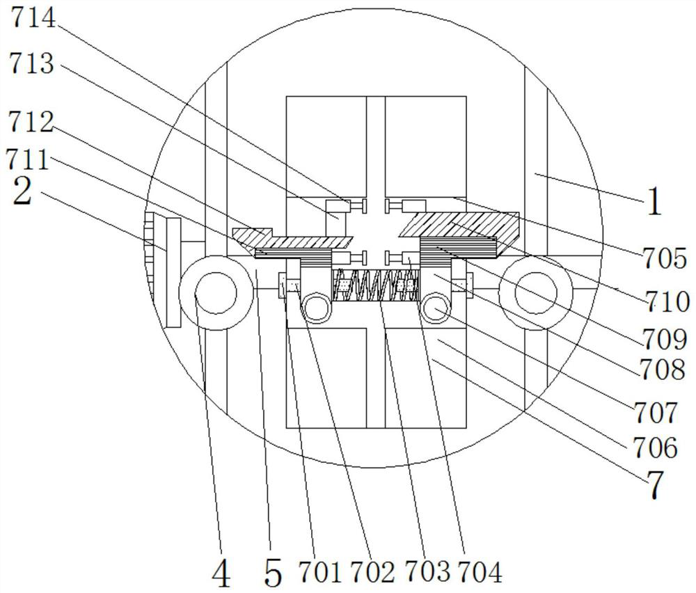
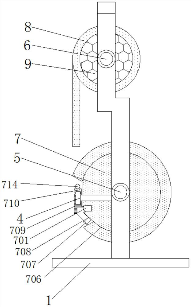
[0028] see Figure 1-4 , an automatic fixed-length rope cutter, including a frame 1 and a cutting mechanism 7, the cutting mechanism 7 includes a fixed block 701, a pin 702, a compression spring 703, a first telescopic rod 704, an arc groove 705, a cutting wheel 706, Screw 707, connecting block 708, first seven-character plate 709, first blade 710, second seven-character plate 711, second blade 712, spacer 713 and second telescopic rod 714;

[0029] The inside of the frame 1 is provided with a cutting wheel 706, the central part of the cutting wheel 706 is fixedly connected with a first major axis 5, and the left and right ends of the first major axis 5 are connected to the left and right ends of the lower end of the frame 1. On the side, the left end of the first long axis 5 is fixedly connected with the first motor 2 , and the first motor 2 is fixed on the left side wall of the frame 1 .

[0030] The frame 1 is used to carry the entire mechanism, and the frame 1 is symmetri...

Embodiment 2

[0042] see figure 1 and 3 , an automatic fixed-length rope cutting device, the upper end of the frame 1 is provided with a second long axis 6, and the left and right ends of the second long axis 6 are connected to the left and right sides of the frame 1;

[0043] A second motor 3 is fixedly connected to the left end of the second long axis 6, and the second motor 3 is fixed to the left side wall of the frame 1;

[0044] The middle part of the second long axis 6 is fixedly sleeved with a roller 9 , and the outer wall of the roller 9 is wound with a loop 8 .

[0045] The middle part of the second major axis 6 is fixedly sleeved with a roller 9, and the outer wall of the roller 9 is wound with a rope loop 8, and the rope is free to fall by rotating the second major axis 6; on the other hand, the second major axis 6 is connected to the second The rotation of the motor 3 is controlled by the motor 3, which makes the structure more simplified.

[0046] The solution in this embodi...


PUM


Abstract

The invention discloses an automatic fixed-length rope cutter, and relates to the field of rope cutters. The automatic fixed-length rope cutter comprises a frame and a cutting mechanism, and the cutting mechanism comprises a fixing block, a pin, a compression spring, a first telescopic rod, an arc-shaped groove, a cutting wheel, a screw, a connecting block, a first 7-shaped plate, a first blade, asecond 7-shaped plate, a second blade, a cushion block and a second telescopic rod; the cutting wheel is arranged in the frame, a first long shaft is fixedly connected to the center of the cutting wheel in a penetrating mode, the left end and the right end of the first long shaft are connected to the left side and the right side of the lower end of the frame in a penetrating mode, a first motor is fixedly connected to the tail end of the left side of the first long shaft, and the first motor is fixed to the side wall of the left side of the frame. According to the automatic fixed-length ropecutter, the problems that segmentation is conducted through existing manual cutting, and the segmentation cutting efficiency is low are solved, when a rope is put into a groove of the cutting wheel, the rope is cut through extrusion of rolling wheels on the two sides, and the cutting efficiency is high.

Description

Technical field: [0001] The invention relates to the field of rope cutters, in particular to an automatic fixed-length rope cutter. Background technique: [0002] The appearance of rope can be traced back tens of thousands of years ago. When humans began to have the simplest tools, they twisted and twisted grass or small branches into ropes. People use it to bind wild animals, fasten thatched huts, make belts to tie grass skirts, etc. With people's perfect pursuit of life and the rapid development of industry, the rope has been braided from several twisted strands to two strands, three strands, eight strands, sixteen strands and twenty-four strands, which makes the surface of the rope more and more textured. The more detailed and beautiful it is, it can be woven together by one color or multiple colors regularly, the colors are more attractive, and the materials are available, such as hemp, brown, polypropylene yarn, polyester yarn, cotton yarn, nylon yarn and other fibers...

Claims


Application Information

Patent Timeline
Patent Type & Authority Applications(China)
IPC IPC(8): B26D1/06B26D5/08B26D7/02B26D7/28
CPCB26D1/06B26D5/086B26D7/02B26D7/28
Inventor 段照林
Owner 安徽省乐悠悠户外用品有限公司
Learn More