Boundary-layer-free separation air inlet channel

A technology of air inlet and boundary layer, which is applied in the field of aviation air inlet, can solve problems such as the decrease of radar stealth performance, the difficulty of manufacturing air inlet, and the increase of aircraft aerodynamic resistance, so as to eliminate the effect of angle emitter and improve the stealth effect , Reduce the effect of windward area and drag

Active Publication Date: 2020-11-17
SICHUAN AEROSPACE ZHONGTIAN POWER EQUIP CO LTD
View PDF12 Cites 2 Cited by
  • Summary
  • Abstract
  • Description
  • Claims
  • Application Information

AI Technical Summary

Problems solved by technology

[0005] Based on the above problems, the object of the present invention is to: provide a kind of air inlet without boundary layer partition, which is used to solve the problem that the boundary layer partition of the air inlet in the prior art increases the windward area of ​​the aircraft, thereby making the aerodynamic The resistance increases, the radar stealth performance decreases, and the manufacture of the air inlet is difficult

Method used


Image

  • Boundary-layer-free separation air inlet channel
  • Boundary-layer-free separation air inlet channel
  • Boundary-layer-free separation air inlet channel

Examples


Embodiment 1

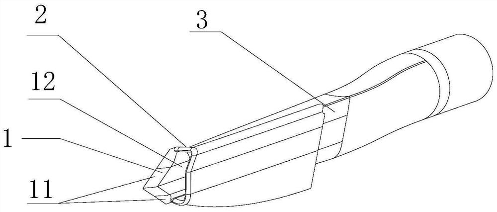
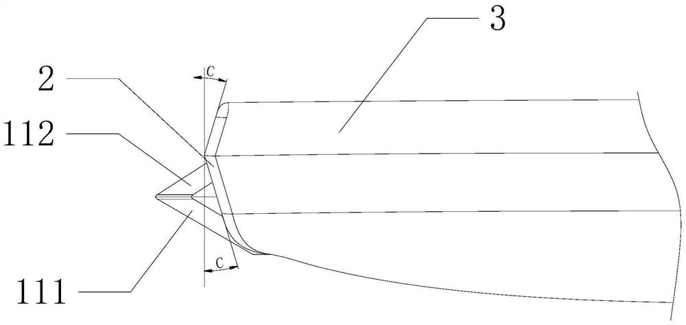
[0023] like Figure 1-3 As shown, an air inlet without a boundary layer, including an air inlet pipe 3, a lip 2 and a bulge 1, which are sequentially formed as one, and the bulge 1 includes a step surface 11 and a main surface 12 of the bulge formed integrally with each other. , the stepped surface 11 includes an upper stepped surface 112 and a lower stepped surface 111, and the edge of the lip 2 is provided with a sweep angle.

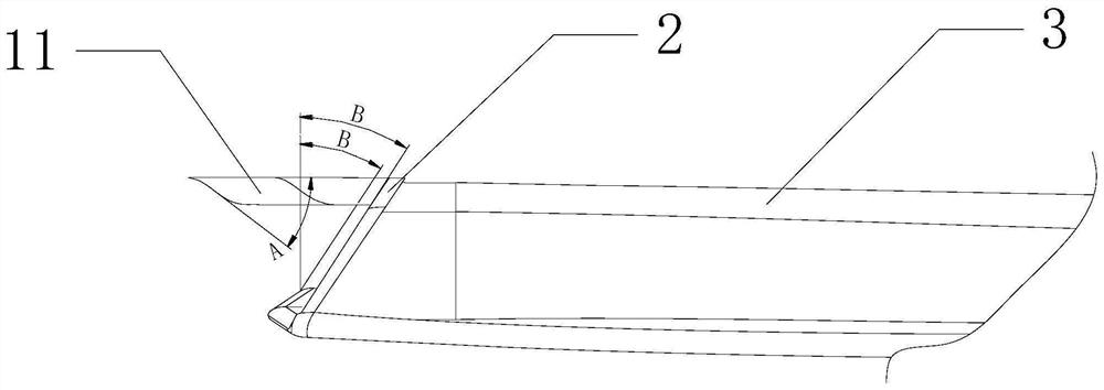
[0024] Wherein, the upper stepped surface 112 and the lower stepped surface 111 are both planes. The included angles between the upper step surface 112 , the lower step surface 111 and the heading are all A, and A is preferably 30°-45°.

[0025] The main surface of the bulge 1 is parallel to the course, and the connection between the main surface 12 of the bulge 12 and the step surface 11 is rounded.

[0026] The height of the main surface 12 of the bulge is 40mm.

[0027] The sweep angle includes a top view sweep angle B and a front view sweep ang...

Embodiment 2

[0030] like Figure 1-3 As shown, an air inlet without a boundary layer, including an air inlet pipe 3, a lip 2 and a bulge 1, which are sequentially formed as one, and the bulge 1 includes a step surface 11 and a main surface 12 of the bulge formed integrally with each other. , the stepped surface 11 includes an upper stepped surface 112 and a lower stepped surface 111, and the edge of the lip 2 is provided with a sweep angle.

[0031] Wherein, the upper step surface 112 and the lower step surface 111 are both planes, and the included angles between the upper step surface 112, the lower step surface 111 and the heading are A, A is preferably 33°, and there is The rounding of R10 or other curves transition smoothly, and there is rounding of R10 between the body and the intersection of the upper step surface 112 and the lower step surface 111. The height of the main surface 12 of the bulge is 40mm, and the bulge The main face 12 is parallel to the heading.

[0032] The sweep ...


PUM


Abstract

The invention relates to the technical field of aviation air inlet channels, in particular to a boundary-layer-free separation channel air inlet channel which is used for solving the problems that inthe prior art, a boundary layer separation channel of an air inlet channel increases the windward area of an airplane, so that the aerodynamic resistance of the airplane is increased, the radar stealth performance is reduced, and the air inlet channel is difficult to manufacture. The boundary-layer-free separation channel air inlet channel comprises an air inlet pipeline, a lip and a bulge which are sequentially formed into a whole, the bulge comprises a step face and a bulge main face which are mutually formed into a whole, the step face comprises an upper step face body and a lower step facebody, and a sweepback angle is arranged on the edge of the lip. A boundary layer separation channel is omitted, the angle emitter effect of boundary layer separation channel electromagnetic waves iseliminated, the windward area and resistance of an airplane are reduced, and manufacturing is easier; the sweepback angle design is adopted for the lip and the bulge, the electromagnetic wave mirror surface effect under the main use posture of an airplane is reduced, and therefore the stealth effect of the lip is improved.

Description

technical field [0001] The invention relates to the technical field of aviation air intakes, in particular to an air intake without a boundary layer partition. Background technique [0002] Aircraft are instruments that fly in the atmosphere or outside the atmosphere. They rely on the static buoyancy of the air or the aerodynamic force generated by the relative motion of the air to lift into the air. High-speed aircraft are the most common and widely used type of air-breathing aircraft. [0003] In the prior art, the air inlet includes an air inlet surface located at the front end of the air inlet, an inner channel of the air inlet extending backward from the air inlet surface, a lip cover surrounding the air inlet surface, and a fuselage connected to the air inlet surface. part, the air inlet surface includes a first mouth surface located outside the fuselage part and a second mouth surface located inside the fuselage part, the lip cover includes the main lip cover and the ...

Claims


Application Information

Patent Timeline
Patent Type & Authority Applications(China)
IPC IPC(8): B64D33/02
CPCB64D33/02
Inventor 刘博宋勇李世秋谢文忠于红勇何国忠刘驰王荣童凯李晓飞
Owner SICHUAN AEROSPACE ZHONGTIAN POWER EQUIP CO LTD
Why Eureka
Try Eureka