A multi-strand twisting machine

A twisting machine and twisting technology, applied in textiles and papermaking, etc., can solve the problem that multiple strands of thin threads cannot be evenly arranged, and achieve the effect of avoiding uneven strength and even hanging.

Active Publication Date: 2021-07-02
TAIZHOU LAI & KE INTELLIGENT TECH CO LTD
View PDF11 Cites 0 Cited by
  • Summary
  • Abstract
  • Description
  • Claims
  • Application Information

AI Technical Summary

Problems solved by technology

[0002] The invention with the publication number of CN110485008A discloses a tension self-adjusting multi-strand twisting machine, the structure of which includes a multi-strand twisting machine, a wiring device, a twisting groove, a thread stand, a tensioner, an infrared detection sensor for thread breakage, and a multi-strand twisting machine. The thread combiner, the wire outlet barrel, the yarn storage tank, the thread gripper, and the wiring device are composed of a shell, a double-wire guide groove, a stringing wheel, a wire-inserting mechanism, and a thread-pressing mechanism. Twisted textile thread, used for continuous twisting work after wiring, detects whether there is a broken thread through the broken thread infrared detection sensor, and then uses the thread insertion mechanism to cooperate with the thread pressing mechanism to connect the spare twisted textile thread with the broken twisted textile thread Twisting, and the two textile threads are lifted up by the wire wheel to avoid being affected during the wiring. This design allows the multi-strand twisting machine to continue to work in the case of thread breaks, and does not need to turn off the power, and does not require manual work. Standing guard for a long time; but the multi-strand thin wires clamped by the thread clamp of the invention cannot be evenly arranged

Method used


Image

  • A multi-strand twisting machine
  • A multi-strand twisting machine
  • A multi-strand twisting machine

Examples


specific Embodiment approach 1

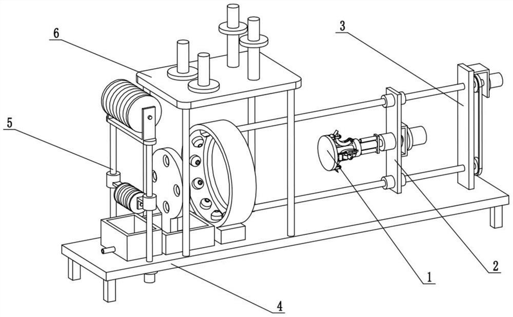
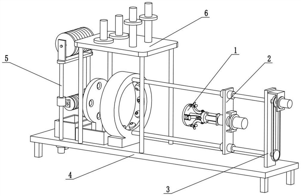
[0025] Combine below Figure 1-8 Describe this embodiment. The present invention relates to the field of textile technology, more specifically, a multi-strand twisting machine, including a suspension automatic telescopic mechanism 1, a twisting thread follow-up tensioning mechanism 2, a tensioning drive mechanism 3, and a position-limiting wetting mechanism. Mechanism 4, guide immersion mechanism 5 and wire reel placement follow-up mechanism 6, wire reel placement follower mechanism 6 is fixedly connected on the limit wetting mechanism 4, guide immersion mechanism 5 is fixedly connected on the limit wetting mechanism 4, pull The tightening drive mechanism 3 is fixedly connected to the limit wetting mechanism 4, the twisted thread follow-up tensioning mechanism 2 is connected to the tensioning drive mechanism 3 through threads, and the suspension automatic telescopic mechanism 1 is fixedly connected to the twisted thread follow-up tensioning mechanism 2 superior.

[0026] Plac...

specific Embodiment approach 2

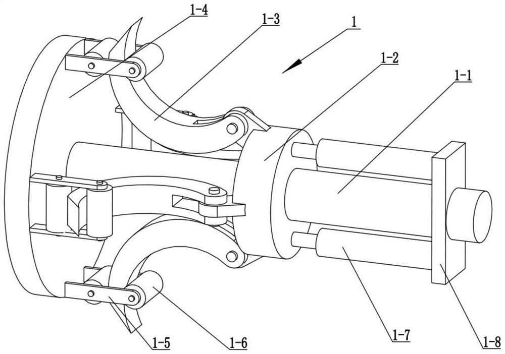
[0028] Combine below Figure 1-8 Describe this embodiment, this embodiment will further explain the first embodiment, the suspension automatic telescopic mechanism 1 includes a horizontal rotating rod 1-1, a moving sleeve 1-2, an arc-shaped telescopic hook 1-3, and a circular top plate 1 -4, limit telescopic frame 1-5, auxiliary limit roller 1-6, mobile cylinder 1-7 and cylinder mounting plate 1-8, cylinder mounting plate 1-8 is fixedly connected to the right side of horizontal rotating rod 1-1, The moving shaft sleeve 1-2 is slidingly connected on the horizontal rotating rod 1-1, and the right ends of the two moving cylinders 1-7 are respectively fixedly connected to the upper and lower ends of the cylinder mounting plate 1-8, and the moving shaft sleeve 1-2 is fixedly connected to the two On the cylinder rod of a moving cylinder 1-7, a plurality of arc-shaped telescopic hooks 1-3 are all rotatably connected to the moving bushing 1-2, and the circular top plate 1-4 is fixedly...

specific Embodiment approach 3

[0031] Combine below Figure 1-8 Describe this embodiment, this embodiment will further explain embodiment two, described twisted thread follow-up tensioning mechanism 2 includes tensioning riser 2-1, motor gantry 2-2, twisting motor 2-3, The tensioning threaded sleeve 2-4 and the rotating sleeve 2-5, the rotating sleeve 2-5 is rotatably connected to the middle of the tensioning vertical plate 2-1, and the two tensioning threaded sleeves 2-4 are respectively fixedly connected to the tensioning vertical plate The upper and lower ends of 2-1, the motor gantry 2-2 is fixedly connected to the tensioning vertical plate 2-1, the twisting motor 2-3 is fixedly connected to the motor gantry 2-2, and the rotating sleeve 2-5 is fixed Be connected on the output shaft of the twisting motor 2-3, and the right end of the horizontal rotating rod 1-1 is fixedly connected in the rotating sleeve 2-5.

[0032] The twisting motor 2-3 drives the rotating sleeve 2-5 to rotate, and the rotating slee...


PUM


Abstract

The invention relates to the technical field of textiles, and more specifically relates to a multi-strand twisting machine, which can evenly arrange a plurality of thin threads for twisting operations. Including suspension automatic telescopic mechanism, twisting follow-up tensioning mechanism, tensioning drive mechanism, limit wetting mechanism, guiding immersion mechanism and wire reel placement follow-up mechanism, the moving sleeve is driven by the moving cylinder to slide on the horizontal rotating rod, Make the moving bushing drive multiple arc-shaped telescopic hooks to protrude from multiple auxiliary limit rollers to hang multiple strands of thin wire, and at the same time make the suspension of thin wire more uniform and avoid twisting during the twisting process The thickness of the final thick thread is not uniform enough to avoid uneven strength of the twisted thick thread.

Description

technical field [0001] The invention relates to the technical field of textiles, in particular to a multi-strand twisting machine. Background technique [0002] The invention with the publication number of CN110485008A discloses a tension self-adjusting multi-strand twisting machine, the structure of which includes a multi-strand twisting machine, a wiring device, a twisting groove, a thread stand, a tensioner, an infrared detection sensor for thread breakage, and a multi-strand twisting machine. The thread combiner, the wire outlet barrel, the yarn storage tank, the thread gripper, and the wiring device are composed of a shell, a double-wire guide groove, a stringing wheel, a wire-inserting mechanism, and a thread-pressing mechanism. Twisted textile thread, used for continuous twisting work after wiring, detects whether there is a broken thread through the broken thread infrared detection sensor, and then uses the thread insertion mechanism to cooperate with the thread pres...

Claims


Application Information

Patent Timeline
Patent Type & Authority Patents(China)
IPC IPC(8): D01H13/30D01H13/04
CPCD01H13/04D01H13/30D01H13/302D01H13/306
Inventor 高梦竹
Owner TAIZHOU LAI & KE INTELLIGENT TECH CO LTD
Why Eureka
Try Eureka