Placing vehicle convenient for automatically collecting and placing traffic cones
An automatic retractable and traffic cone technology, which is applied in the field of placed vehicles, can solve the problems of low construction efficiency, complex structure of placed vehicles, and complex structures.
- Summary
- Abstract
- Description
- Claims
- Application Information
AI Technical Summary
Problems solved by technology
Method used
Image

Examples
Embodiment 1
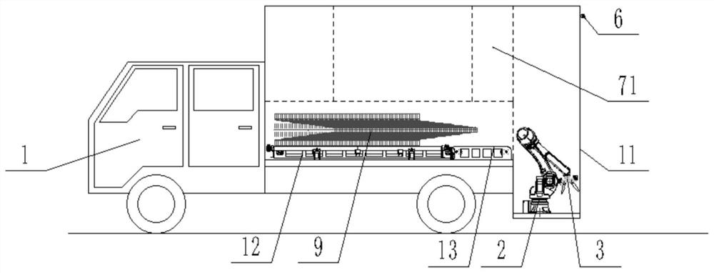
[0038] Such as figure 1 As shown in the figure, a vehicle for automatically retracting traffic cones includes a truck body 1 and a compartment 11 arranged at the rear of the truck body 1. A traffic cone storage device 12 for storing traffic cones is provided on the front side of the compartment 11. , the traffic cone storage device 12 is adjacent to the traffic cone conveying device 13 for transporting the traffic cone, the rear side of the compartment 11 is provided with a traffic cone placement unit, the traffic cone placement unit includes a base 4 fixedly connected to the compartment 11, on the base 4 A six-axis robot 2 is arranged on the road surface, and the six-axis robot 2 is used to transport the traffic cone conveying device 13 to a designated position and placed on the road. The six-axis robot 2 is also provided with a traffic cone fixture for grabbing the traffic cone. 3. The traffic cone storage device 12, the traffic cone conveying device 13, the six-axis robot 2...
Embodiment 2
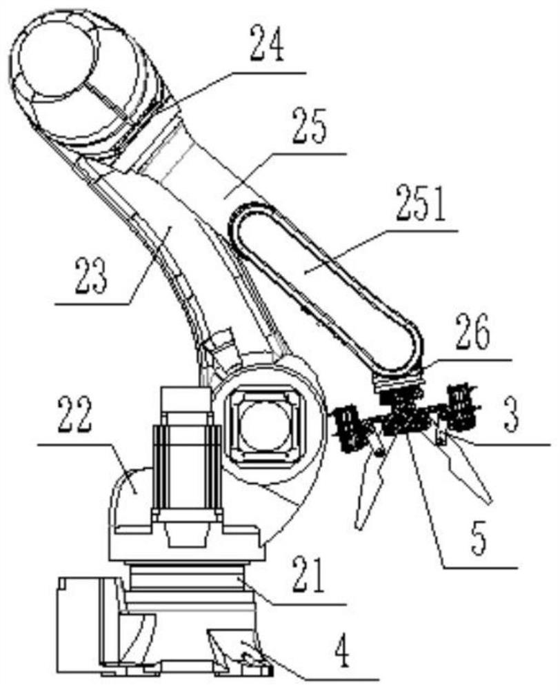
[0041] Such as figure 2 As shown, on the basis of Embodiment 1, the six-axis robot 2 includes a first axis arm 21, a second axis arm 22, a third axis arm 23, a fourth axis arm 24, a fifth axis arm 25 and a sixth axis arm Arm 26, the bottom end of the first shaft arm 21 is rotationally connected with the top of the base 4, the bottom end of the second shaft arm 22 is welded to the top end of the first shaft arm 21, and the top and bottom ends of the third shaft arm 23 are equipped with Pin shaft, the bottom end of the third shaft arm 23 is connected with the side of the second shaft arm 22 by a pin shaft, the top of the third shaft arm 23 is connected with the bottom of the fourth shaft arm 24 by a shaft pin, and the fifth shaft arm 25 One end is embedded in the fourth shaft arm 24 and fits with the inner wall of the fourth shaft arm 24. The other end of the fifth shaft arm 25 is provided with a U-shaped opening 251, and the U-shaped opening 251 is provided with a sixth pendul...
Embodiment 3
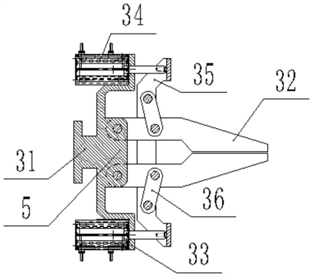
[0044] Such as image 3 and Figure 4 As shown, on the basis of Embodiment 2, wherein the traffic cone clamp 3 is provided with a visual detection device 5, the visual detection device 5 includes a support frame 51 fixedly installed on the traffic cone clamp, and the first frame on the top of the support frame 51 The camera 52, and the infrared sensor 53 located at the middle part of the support frame 51, the six-axis robot 2, the traffic cone fixture 3, the first camera 52 and the infrared sensor 53 are all electrically connected with the control device, and the infrared sensor is used to sense the traffic cone. The position and state of the traffic cone, the first camera is used to collect the placement state of the traffic cone (upright or tilted). In specific use, when the traffic cone needs to be placed, the operator starts the traffic cone placement mode. At this time, Obtain the position and state of the traffic cone through the infrared sensor and the first camera, an...
PUM
 Abstract
Description
Claims
Application Information
 - R&D
- Intellectual Property
- Life Sciences
- Materials
- Tech Scout
- Unparalleled Data Quality
- Higher Quality Content
- 60% Fewer Hallucinations
Browse by: Latest US Patents, China's latest patents, Technical Efficacy Thesaurus, Application Domain, Technology Topic, Popular Technical Reports.
© 2025 PatSnap. All rights reserved.Legal|Privacy policy|Modern Slavery Act Transparency Statement|Sitemap|About US| Contact US: help@patsnap.com