
Metal mine underground ventilation device

A technology for underground ventilation and mining, which is applied in mine/tunnel ventilation, safety devices, mining equipment, etc., can solve problems such as unfavorable air contact, inconvenience for sufficient and rapid ventilation of underground air in metal mines, and unfavorable metal dust collection and treatment, etc. The effect of ventilation efficiency

Active Publication Date: 2020-11-17
中核二十五建设有限公司
View PDF7 Cites 0 Cited by
  • Summary
  • Abstract
  • Description
  • Claims
  • Application Information

AI Technical Summary

Problems solved by technology

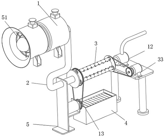
[0003] When the existing mechanical method is used to ventilate the underground of metal mines, through the main fan connected to the outside of the mine, the main fan passes the outside wind into the mine, and the air in the mine is ventilated and replaced. At the same time, through the processing equipment of the air pump, Exhaust the waste gas in the mine out of the mine, but in the ventilation process, the mouth of the mine is ventilated. Since the ventilation pipe has a certain length, it is only ventilated through the mouth of the pipe, and the air from the outside is relatively slow. It is not conducive to the outside ventilation air to fully contact with the air in the mine after entering the mine, and it is not convenient to fully and quickly ventilate the underground air of the metal mine, and to ventilate through the nozzle, the metal dust mixed in the underground air is concentrated in the pipe It is not conducive to the collection and treatment of metal dust distributed in the ventilation ducts. Therefore, we propose a metal mine underground ventilation device

Method used


Image

  • Metal mine underground ventilation device
  • Metal mine underground ventilation device
  • Metal mine underground ventilation device

Examples


Embodiment Construction

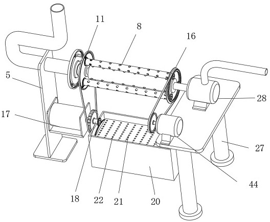
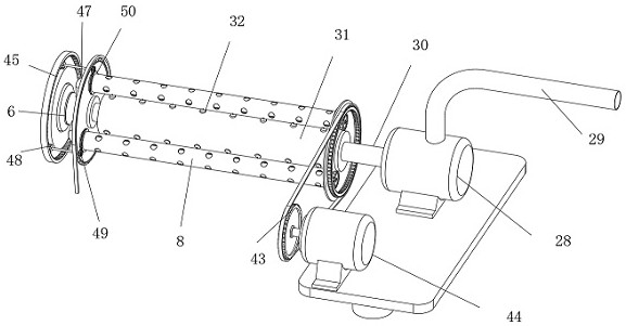
[0028] The following will clearly and completely describe the technical solutions in the embodiments of the present invention with reference to the accompanying drawings in the embodiments of the present invention. Obviously, the described embodiments are only some, not all, embodiments of the present invention. Based on the embodiments of the present invention, all other embodiments obtained by persons of ordinary skill in the art without making creative efforts belong to the protection scope of the present invention.

[0029] see Figure 1-12 , the present invention provides a technical solution: an underground ventilation device for metal mines. This solution solves the problem that only the ventilation pipe openings are used for ventilation when the existing metal mines are ventilated, and the ventilation efficiency is low, and during the ventilation process, the air mixed with It is not convenient to deal with the metal dust in time. The design in this scheme includes a m...


PUM


Abstract

The invention discloses a metal mine underground ventilation device. The device comprises a main draught fan, the output end of the main draught fan communicates with an air inlet pipeline, one end ofthe air inlet pipeline is connected with an underground ventilation assembly which is capable of achieving underground ventilation in multiple directions to achieve even ventilation, and a metal dustdisposal assembly which is for conducting screening treatment of metal dust is connected with the bottom of the underground ventilation assembly. According to the device, rotary ventilation is achieved through the arrangement of the underground ventilation assembly; while multiple ventilation pipelines realizes rotating ventilation, a rotation assembly drives single ventilation pipelines to realize rotating ventilation, so the ventilation pipelines make full contact with underground air in the ventilation process conveniently and the ventilation efficiency is improved conveniently; and meanwhile in the ventilation process of the underground ventilation assembly, the metal dust treatment assembly is driven conveniently, so the metal dust after dust reduction is subjected to screening treatment in time in a convenient mode, and the metal dust can be subjected to centralized collection and treatment conveniently.

Description

technical field [0001] The invention relates to the technical field of mine ventilation equipment, in particular to an underground ventilation device for metal mines. Background technique [0002] The basic tasks of mine ventilation are: to supply enough fresh air underground to meet the oxygen needs of personnel; to dilute harmful gases and dust underground to ensure safe production; to adjust the underground climate and create a good working environment. In order to distribute the underground air flow along the designated route, it is necessary to build structures that guide and control the air flow in certain roadways, that is, ventilation facilities, which are divided into facilities that guide the air flow and block the air flow. The ventilation system of new large-scale mines is mainly of diagonal type and partition type, and the production mine of reconstruction and expansion is mainly of mixed type. For the ventilation in metal mines, it is necessary to consider that...

Claims


Application Information

Patent Timeline
IPC IPC(8): E21F1/08E21F1/04E21F5/00E21F5/04E21F5/20
CPCE21F1/08E21F1/04E21F5/00E21F5/04E21F5/20Y02B10/40
Inventor 陈清尧
Owner 中核二十五建设有限公司
Learn More