
LNG high-pressure pump
A high-pressure pump and high-pressure pipe technology, applied in the field of high-pressure pumps, can solve the problems of unstable transmission, energy waste, pump shaft fracture, etc., and achieve the effects of reducing safety accidents, convenient detection, and increasing strength
- Summary
- Abstract
- Description
- Claims
- Application Information
AI Technical Summary
Problems solved by technology
Method used
Image

Examples
Embodiment Construction
[0021] The present invention will be described in detail below in conjunction with the accompanying drawings and embodiments.
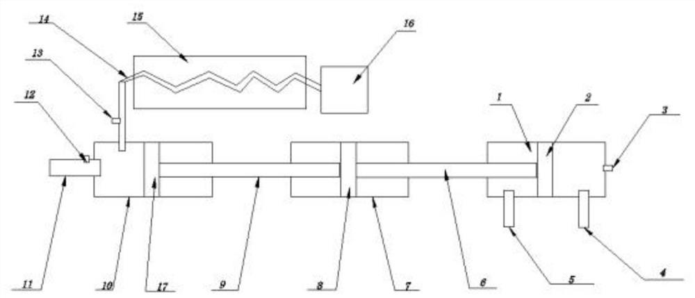
[0022] refer to figure 1 , an LNG high-pressure pump, comprising a hydraulic chamber 1, a first vacuum chamber 7 and a second vacuum chamber 10, a first guide ring 2 is installed inside the hydraulic chamber 1, a second guide ring 8 is installed inside the first vacuum chamber 7, A third guide ring 17 is installed inside the second vacuum chamber 10, the left side of the first guide ring 2 is connected by the first pump shaft 6 and the right side of the second guide ring 8, and the left side of the second guide ring 8 is connected by the second The pump shaft 9 is connected to the right side of the third guide ring 17;
[0023] The hydraulic chamber 1 on the left side of the first guide ring 2 is equipped with a first hydraulic inlet and outlet 4, and the hydraulic chamber 1 on the right side of the first guide ring 2 is equipped with a second hydrau...
PUM
 Abstract
Description
Claims
Application Information