Control method for preventing ignition deflagration of gas stove and gas stove

A control method and technology for gas stoves, which are applied in the field of gas stoves, can solve the problems of small aperture of an inner ring nozzle, deflagration, deflagration, etc., and achieve the effect of avoiding deflagration.

Inactive Publication Date: 2020-11-17
VATTI CORP LTD
0 Cites 3 Cited by

AI-Extracted Technical Summary

Problems solved by technology

[0002] At present, most of the ignition methods used in embedded household gas stoves are pulse ignition, which first ignites the inner ring, and then transfers the fire to the outer ring through the inner ring; however, the nozzles of the inner ring usually have small apertures, small loads, and lo...

Method used

The present embodiment at first collects the ignition signal of gas stove, when can collect the inner ring gas channel of gas stove when ignition signal can be collected; Then collect the ignition state of gas stove inner ring, and control outer ring according to described ignition state The on-off of the gas channel; the on-off of the outer ring gas channel is controlled by the ignition state of the inner ring, which avoids the phenomenon of deflagrat...

Abstract

The invention discloses a control method for preventing ignition deflagration of a gas stove and the gas stove. The control method for preventing ignition deflagration of the gas stove comprises the following steps that S1, an ignition signal is collected, entering S2 is performed when the ignition signal is collected, otherwise, collecting continues; S2, an inner ring gas channel of the gas stoveis opened; and S3, the ignition state of an inner ring of the gas stove is collected, and an outer ring gas channel is controlled to be connected or disconnected according to the ignition state. According to the control method, firstly, the ignition signal of the gas stove is collected, and when the ignition signal can be collected, the inner ring gas channel of the gas stove is opened; then, theignition state of the inner ring of the gas stove is collected, and the outer ring gas channel is controlled to be connected or disconnected according to the ignition state; and the outer ring gas channel is controlled to be connected or disconnected according to the ignition state of the inner ring, and the the deflagration phenomenon generated after the outer ring gas channel is connected too early and a large amount of gas is collected is avoided.

Application Domain

Domestic stoves or rangesGaseous fuel burner +1

Technology Topic

Automotive engineeringProcess engineering +4

Image

  • Control method for preventing ignition deflagration of gas stove and gas stove
  • Control method for preventing ignition deflagration of gas stove and gas stove
  • Control method for preventing ignition deflagration of gas stove and gas stove

Examples

  • Experimental program(2)

Example Embodiment

[0034] Example 1
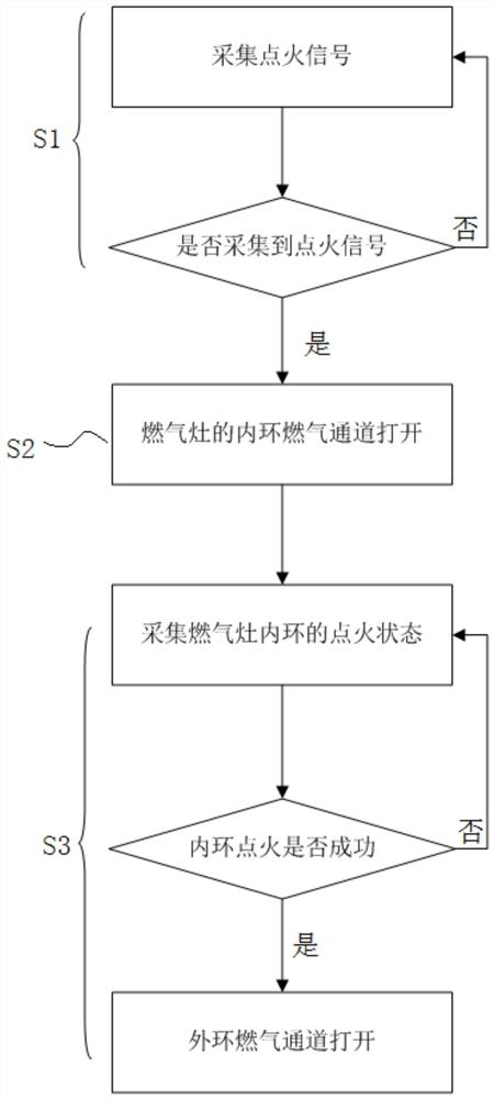
[0035] Embodiment 1 of the present invention provides a control method for preventing ignition and deflagration of a gas stove, such as Figure 1 As shown in, it is implemented according to the following steps:
[0036] S1, collecting ignition signals, and when the ignition signals are collected, going to S2, otherwise, continuing to collect;
[0037] Specifically, the controller collects the state of the cock valve of the gas stove, and enters S2 when the cock valve is pressed, otherwise, the controller continues to collect the state of the cock valve of the gas stove;
[0038] The controller collects whether the user presses the valve stem of the plug valve, if so, it proves that the user is igniting, and then it goes to S2, otherwise, it continues to collect;
[0039] S2, opening the inner ring gas channel of the gas stove;
[0040] It should be noted that the existing ignition mode is to ignite the inner ring first, and then transmit the fire to the outer ring through the inner ring, so the gas channel of the outer ring is closed at this time, and the gas channel of the inner ring is controlled to open by the total solenoid valve of the gas cooker;
[0041] S3, collecting the ignition state of the inner ring of the gas stove, and controlling the on-off of the outer ring gas channel according to the ignition state;
[0042] Specifically, when the ignition state of the inner ring is successful, the outer ring gas channel is opened; Otherwise, continue to collect the ignition state of the inner ring of the gas stove.
[0043] In one embodiment, the on-off of the outer ring gas channel is controlled in S3, specifically:
[0044] The on-off of the outer ring gas channel is controlled by an electromagnetic valve arranged on the outer ring gas channel, and when the electromagnetic valve is in a valve suction state, the outer ring gas channel is opened, otherwise, the outer ring gas channel is disconnected.
[0045] In addition, the ignition state of the inner ring of the gas stove is collected in S3, specifically:
[0046] Sensing whether the ignition of the inner ring is successful through an induction needle arranged in the inner ring.
[0047] In this embodiment, firstly, the ignition signal of the gas stove is collected, and when the ignition signal can be collected, the inner ring gas channel of the gas stove is opened; Then, the ignition state of the inner ring of the gas range is collected, and the on-off of the outer ring gas channel is controlled according to the ignition state; The on-off of the outer ring gas channel is controlled by the ignition state of the inner ring, which avoids the deflagration phenomenon after the outer ring gas channel is turned on prematurely to gather a large amount of gas.

Example Embodiment

[0048] Example 2
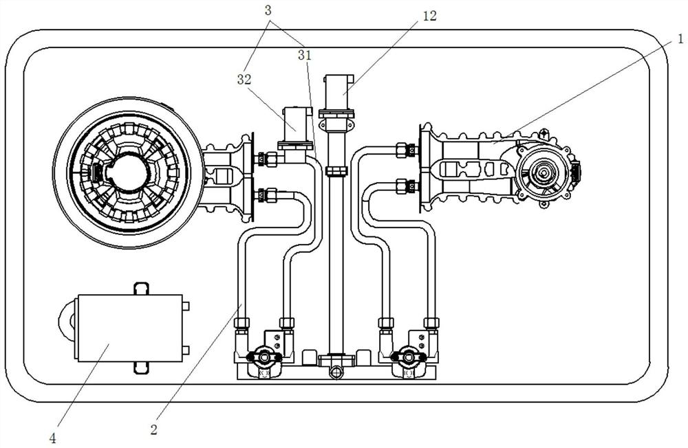
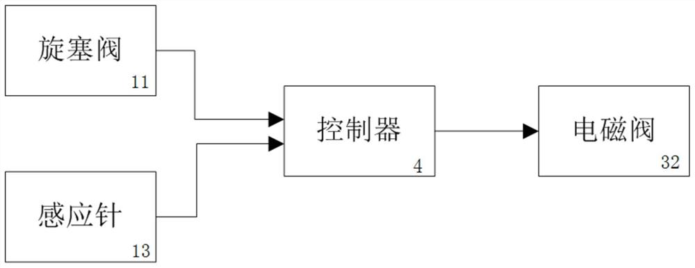
[0049] Embodiment 2 of the present invention provides a gas stove capable of preventing ignition and deflagration, which applies the control method for preventing ignition and deflagration of gas stove described in Embodiment 1, such as Figure 2-3 As shown, it comprises a gas range body 1, an inner ring gas channel 2, an outer ring gas channel 3 and a controller 4, wherein both the inner ring gas channel 2 and the outer ring gas channel 3 provide gas for the gas range body 1, and the input end of the controller 4 is connected with the gas in the inner ring of the body 1, and the output end is connected with the outer ring gas channel 3; The controller 4 controls the on-off of the outer ring gas channel 3 according to the ignition state of the inner ring;
[0050] In this way, with the above structure, when the gas range body 1 needs to be ignited, the controller 4 receives a signal to control the inner ring gas channel 2 to be opened, and when the inner ring is successfully ignited, the outer ring gas channel 3 is opened, and the fire of the inner ring will be transmitted to the outer ring, so that the ignition is successful.
[0051] In this process, the opening time of the outer ring gas channel 3 is very important, and the outer ring gas channel 3 will not be opened until the inner ring is successfully ignited, thus avoiding the deflagration phenomenon after the outer ring gas channel 3 is turned on prematurely to gather a large amount of gas.
[0052] The outer ring gas channel 3 includes a gas pipe 31 and an electromagnetic valve 32, and the electromagnetic valve 32 is arranged on the gas pipe 31 to control the opening and closing of the gas pipe 31.
[0053] In this way, when the controller 4 controls the solenoid valve 32 to be in the valve suction state, the gas pipe 31 is turned on and the outer ring gas channel 3 is opened;
[0054] When the controller 4 controls the solenoid valve 32 to be closed, the gas pipe 31 is disconnected and the outer ring gas channel 3 is closed.
[0055] The gas range body 1 comprises a plug valve 11 and a general solenoid valve 12, wherein the plug valve 11 is connected with a controller 4, and when the valve stem of the plug valve 11 is pressed, the controller 4 controls the inner ring gas channel 2 to open; The main solenoid valve 12 is used for controlling whether the gas cooker body 1 is connected with gas;
[0056] Specifically, when the inner ring gas passage 2 is successfully ignited, the electromagnetic valve 32 keeps the valve suction state, and the outer ring gas passage 3 is opened; When the ring fire is extinguished after cooking, the controller 4 controls the solenoid valve 32 to close.
[0057] In order to enable the controller 4 to accurately control when the solenoid valve 32 is closed, the gas range body 1 further comprises an induction needle 13 arranged in the inner ring;
[0058] The induction needle 13 is connected with the controller 4, and when the induction needle 13 senses that the ignition is successful, the controller 4 controls the electromagnetic valve 32 to suck and turn on the gas pipe 31.
[0059] Working process:
[0060] When the gas stove needs to be ignited, the user presses the valve stem of the plug valve 11. At this time, the controller 4 receives the signal, controls and controls the inner ring gas channel 2 to be opened, and the inner ring is ignited. When the induction needle 13 senses the successful ignition of the inner ring, a current is generated to control the electromagnetic valve 32 to be in a sucking state. When the electromagnetic valve 32 is sucked, the gas pipe 31 is connected, the outer ring gas channel 3 is opened, and the inner ring transmits the fire to the outer ring, thus realizing the successful ignition.
[0061] When the user finishes cooking and turns off the fire, the induction needle 13 senses the fire-off signal and transmits the signal to the controller 4. The controller 4 generates a reverse current to turn off the electromagnetic valve 32. At this time, the gas pipe 31 is turned off, and the whole outer ring gas channel 3 is closed, making preparations for the next ignition.
[0062] According to the embodiment, through the mutual cooperation among the gas range body, the inner ring gas channel, the outer ring gas channel and the controller, the connecting time of the outer ring gas channel is limited, and the deflagration phenomenon after the outer ring gas channel is connected prematurely to gather a large amount of gas is avoided.

PUM

no PUM

Description & Claims & Application Information

We can also present the details of the Description, Claims and Application information to help users get a comprehensive understanding of the technical details of the patent, such as background art, summary of invention, brief description of drawings, description of embodiments, and other original content. On the other hand, users can also determine the specific scope of protection of the technology through the list of claims; as well as understand the changes in the life cycle of the technology with the presentation of the patent timeline. Login to view more.
Why Eureka
Try Eureka