
Engine ignition control and fuel injection control methods based on engine cycles

A technology of ignition control and control method, applied in the direction of engine control, automatic control, automatic control, etc., can solve the problems of inability to accurately control engine combustion, poor combustion, unstable operation, etc., to ensure accuracy, improve power performance, injection Oil Phase Precise Effect

Active Publication Date: 2016-12-21
CHONGQING LONCIN MOTOR
View PDF5 Cites 5 Cited by
  • Summary
  • Abstract
  • Description
  • Claims
  • Application Information

AI Technical Summary

Problems solved by technology

[0003] Existing engine ignition control and fuel injection systems generally use operating condition control to control the ignition advance angle and fuel injection quantity of the engine. With the same ignition advance angle and fuel injection volume, this control method cannot achieve precise control of engine combustion under the transient action of the engine. In addition, the current engine fuel injection system generally determines the operating point according to the engine's operating speed and throttle load. , and then calibrate and match the ignition and fuel injection of the EFI system according to the engine performance level, operating state and combustion conditions at the operating point. Unstable operation or poor combustion and other related problems

Method used


Image

  • Engine ignition control and fuel injection control methods based on engine cycles

Examples


Embodiment 1

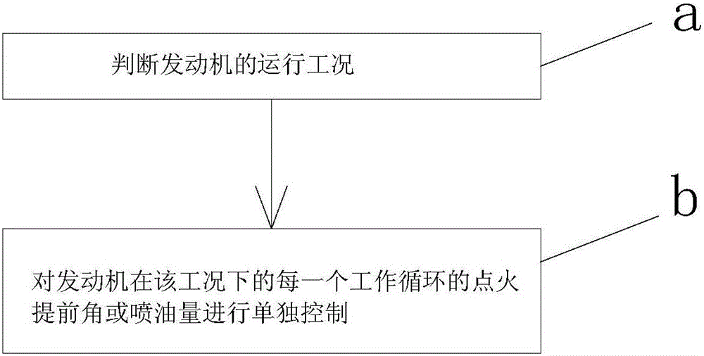
[0025] Embodiment one: figure 1 It is a control logic schematic diagram of the present invention; as shown in the figure: the engine ignition control method based on the engine cycle of the present embodiment includes the following steps:

[0026] a. Judging the operating conditions of the engine; wherein, the method for judging the working conditions can adopt the existing working condition judging method, for example, to judge the working conditions according to parameters such as the throttle opening of the engine and the variation of the throttle opening per unit time ; b. Independently control the ignition advance angle of each working cycle of the engine under this working condition;

[0027]Independent control of the ignition advance angle of each working cycle of the engine under a certain working condition can refine the ignition control of the engine to each working cycle of the engine, thereby making the control parameters of each working cycle of the engine more ac...

Embodiment 2

[0034] Embodiment two: a kind of engine injection control method based on the engine cycle of the present embodiment comprises the following steps: a. judge the operating condition of the engine; wherein, the method for judging the working condition can adopt the existing working condition judging method, For example, according to the parameters such as engine throttle opening and throttle opening variation per unit time, the working condition is judged; b. The fuel injection quantity of each working cycle of the engine under this working condition is individually controlled; The independent control of the fuel injection quantity of each working cycle under a certain working condition can refine the fuel injection control of the engine to each working cycle of the engine, thereby making the control parameters of each working cycle of the engine more accurate and ensuring these control The accuracy of parameters in transitional conditions will ultimately greatly improve the powe...


PUM


Abstract

The invention discloses engine ignition control and fuel injection control methods based on engine cycles. The engine ignition control method comprises the steps of a, judging the operation condition of an engine; and b, and independently controlling the ignition angle of advance and fuel injection quantity of the engine in each working cycle under the condition. According to the engine ignition control and fuel injection control methods, control for ignition and fuel injection of the engine is refined in each working cycle of the engine, control parameters (ignition time, fuel injection pulse width and fuel injection phase position) of all the working cycles of the engine are more accurate, the accuracy of the control parameters under the transition working condition is guaranteed, and finally, the dynamic property, economy and emission level of the engine are improved to the greatest extent.

Description

technical field [0001] The invention relates to an engine ignition and fuel injection control method, in particular to an engine cycle-based engine ignition control and fuel injection control method. Background technique [0002] Both the engine ignition system and fuel injection system are important components of gasoline engines. The ignition system is usually composed of batteries, generators, distributors, ignition coils and spark plugs. When the engine is working, the ignition time has a great impact on the engine's performance Influence, pre-ignition means that the spark plug ignites before the piston reaches the compression top dead center, and ignites the combustible mixture in the combustion chamber. From the moment of ignition until the piston reaches the compression top dead center, the angle that the crankshaft rotates during this period is called the ignition advance angle. The setting of the ignition advance angle plays a decisive role in the power, economy and...

Claims


Application Information

Patent Timeline
Patent Type & Authority Applications(China)
IPC IPC(8): F02P5/145F02D41/30
CPCF02D41/062F02D41/10F02D41/30F02D41/38F02D41/40F02D2200/0404F02P5/145Y02T10/40
Inventor 唐程李庆峰袁旭东李刚李先文
Owner CHONGQING LONCIN MOTOR
Learn More