
Immersed low-nitrogen gas combustion device

A gas combustion and immersion technology, which is applied in the direction of gas fuel burners, burners, combustion methods, etc., can solve the problems of difficult ignition, stable operation cannot be well guaranteed, and increase the generation of nitrogen oxides, so as to improve the system Stability and safety, improvement of overall combustion stability, effect of reducing NOx formation

Pending Publication Date: 2020-12-25
SHANGHAI QIYAO THERMAL ENERGY ENG CO LTD +1
View PDF0 Cites 0 Cited by
  • Summary
  • Abstract
  • Description
  • Claims
  • Application Information

AI Technical Summary

Problems solved by technology

There is a large distance between the ignition device and the burner up and down, resulting in the gas ejected from the burner not being ignited in time, which makes ignition difficult and the success rate is not high
Due to the failure to ignite the gas injected by the burner in time, the combustion chamber is filled with a large amount of mixed gas of air and gas, which will further lead to the occurrence of deflagration, bring safety hazards, and lead to incomplete combustion and nitrogen in the flue gas. The problem of high oxide content; and the pressure pulse in the combustion chamber is large during ignition, so that the stable operation of the entire device cannot be well guaranteed
In addition, the cooling system of the combustion chamber of the existing combustion device is not perfect, resulting in high temperature of the combustion chamber, which further increases the formation of nitrogen oxides in the flue gas, resulting in excessive nitrogen oxide emissions

Method used


Image

  • Immersed low-nitrogen gas combustion device
  • Immersed low-nitrogen gas combustion device
  • Immersed low-nitrogen gas combustion device

Examples


Embodiment Construction

[0065] In the following description, numerous specific details are given in order to provide a more thorough understanding of the present invention. It will be apparent, however, to one skilled in the art that the present invention may be practiced without one or more of these details. In other examples, some technical features known in the art are not described in order to avoid confusion with the present invention.

[0066] For a thorough understanding of the present invention, a detailed description will be set forth in the following description. It is evident that the practice of the embodiments of the invention is not limited to specific details familiar to those skilled in the art. Preferred embodiments of the present invention are described in detail below, however, the present invention may have other embodiments besides these detailed descriptions.

[0067] It should be noted that the terms used herein are for the purpose of describing specific embodiments only, and...


PUM


Abstract

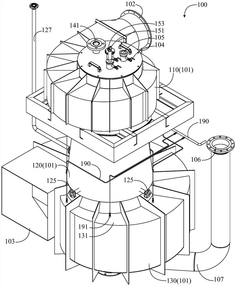
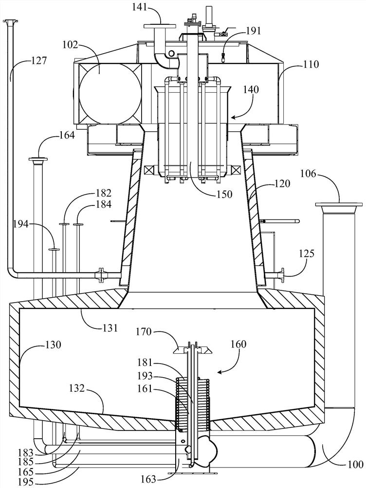
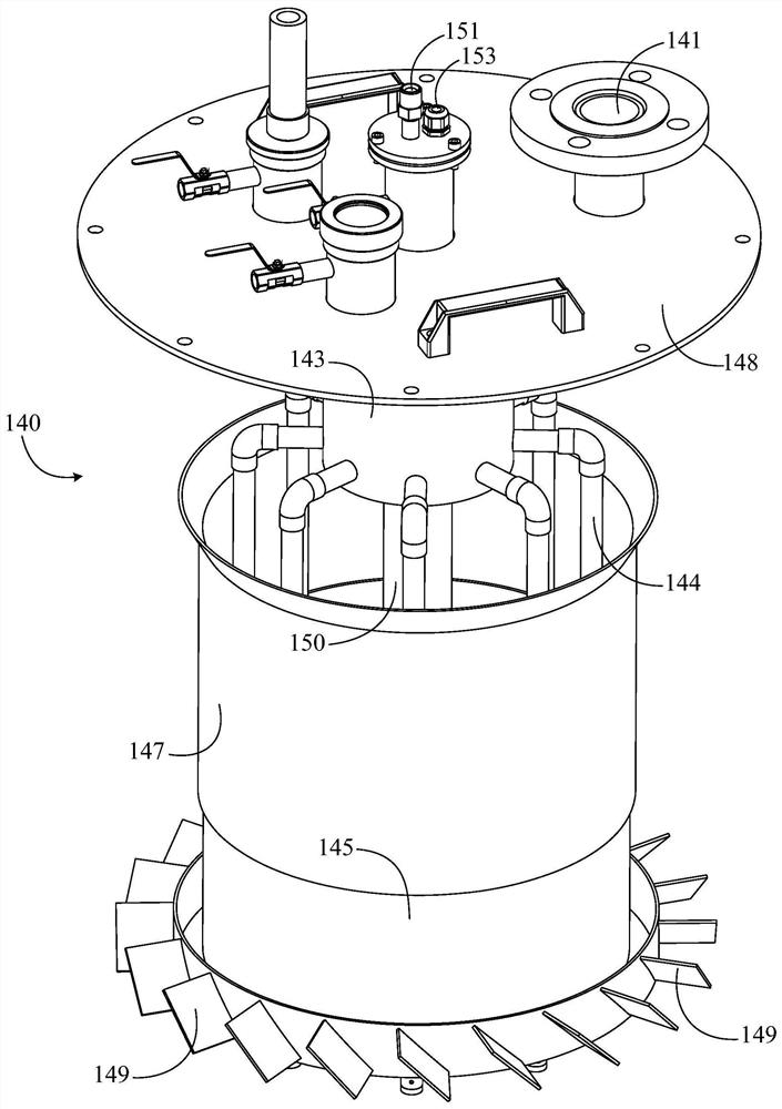
The invention discloses an immersed low-nitrogen gas combustion device. The device comprises a device body, an upper combustor, an ignition gun and a lower combustor, wherein the device body is provided with an upper air inlet, a smoke outlet and a combustion space, the upper combustor is arranged on the upper portion of the device body, the upper combustor is provided with an upper gas inlet andan upper gas nozzle, the ignition gun is arranged on the upper combustor and provided with an ignition gas inlet and a downward ignition gun outlet, the ignition gun outlet and the upper gas nozzle are arranged close to each other, the lower combustor is arranged on the lower portion of the device body and provided with a lower gas inlet pipe and an upward lower gas nozzle, and the lower gas nozzle and the ignition gun outlet are arranged facing each other. According to the device, the lower combustor can be stably ignited, an ignition success rate is improved and reaches up to 100%, the occurrence of a deflagration phenomenon is avoided, an combustion effect is improved, space in a combustion chamber is utilized to the maximum extent, and the overall combustion stability is greatly improved.

Description

technical field [0001] The invention relates to the field of combustion technology, in particular to a submerged low-nitrogen gas combustion device. Background technique [0002] Existing submerged combustion devices generally need to be placed in a water bath during use, so usually a burner is arranged at the bottom of the device, and an ignition device for igniting the burner is arranged at the top of the device to avoid the ignition device Water damage. There is a large distance between the ignition device and the burner up and down, which leads to the failure to ignite the gas injected by the burner in time, which makes ignition difficult and the success rate is not high. Due to the failure to ignite the gas injected by the burner in time, the combustion chamber is filled with a large amount of mixed gas of air and gas, which will further lead to the occurrence of deflagration, bring safety hazards, and lead to incomplete combustion and nitrogen in the flue gas. The pr...

Claims


Application Information

Patent Timeline
IPC IPC(8): F23D14/26F23D14/12F23D14/48F23D14/46F23D23/00
CPCF23D14/12F23D14/26F23D14/46F23D14/48F23D23/00
Inventor 李宇张世程揭涛苏毅李昭新闫玉强杨冰冰李想邬文燕
Owner SHANGHAI QIYAO THERMAL ENERGY ENG CO LTD
Features
  • Generate Ideas
  • Intellectual Property
  • Life Sciences
  • Materials
  • Tech Scout
  • Unparalleled Data Quality
  • Higher Quality Content
  • 60% Fewer Hallucinations
Learn More