
Drop wire cable clamp

A technology for cable clips and household lines, which is applied in the installation of cables, the suspension of cables, the spatial arrangement/configuration of cables, etc., can solve the problems of complicated low-voltage distribution network lines, affecting the insulation performance of lines, and increasing hidden dangers. Achieve the effect of reducing multiple damages, simple structure and not easy to loosen

Pending Publication Date: 2020-11-17
滨州市富阳电力科技有限公司
View PDF0 Cites 0 Cited by
  • Summary
  • Abstract
  • Description
  • Claims
  • Application Information

AI Technical Summary

Problems solved by technology

[0003] The low-voltage distribution network has the characteristics of complex lines and many T contacts. There may be three or more than three lines on a single baseline pole
In recent years, the application of low-voltage cable branch boxes has solved the problem of many T contacts in the line. However, with the rapid development of the rural economy, the coal-to-electricity load and the cooling load in summer have increased significantly. The original lighting power can no longer meet the daily power demand. , the T-connection is growing rapidly, but limited by the capacity and number of branch box switches, the T-connection in the branch box is gradually approaching saturation, and it still needs to be connected from the pole. If each base pole is T-connected with 3 cables For example, according to the standard of double-wire clamp T connection, each insulation layer is damaged in 6 places, which is not beautiful, but also affects the insulation performance of the line, increasing hidden dangers

Method used


Image

  • Drop wire cable clamp

Examples


Embodiment Construction

[0015] A kind of down line cable clip of the present invention is described in detail below in conjunction with accompanying drawing.

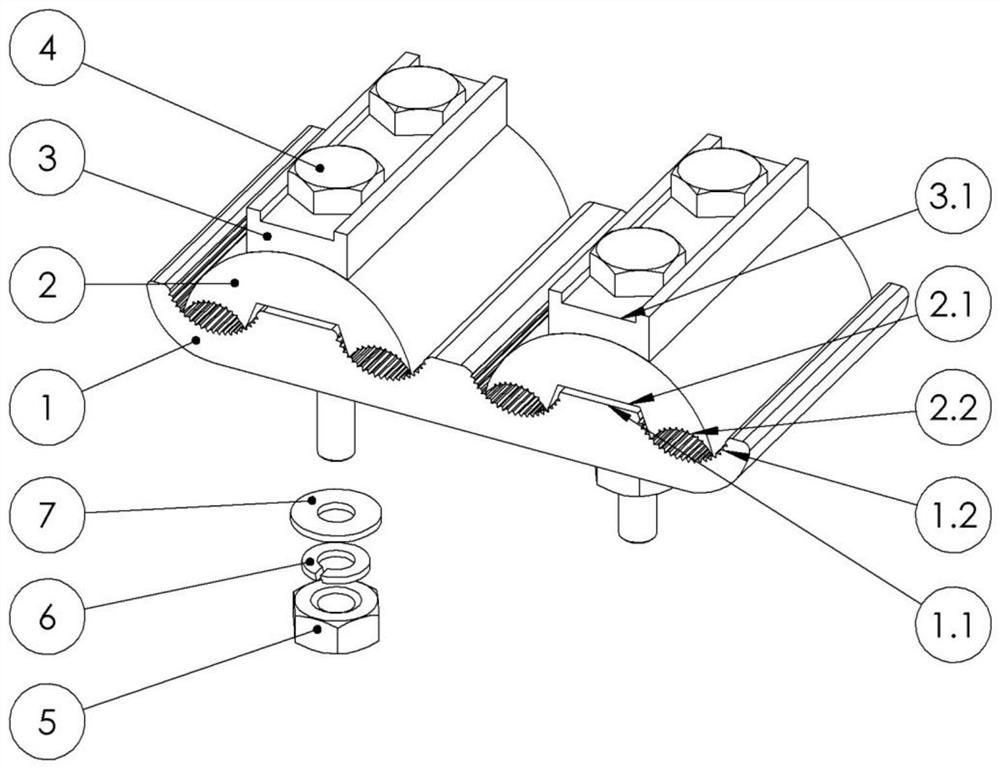
[0016] Such as figure 1 As shown, a cable clamp for lower household lines includes a bottom block 1, and two cover blocks 2 are arranged on the bottom block 1; a bead 3 is arranged on the top of each cover block 2; a screw 4 is arranged in the bead 3, and the screw 4 runs through the bottom block 1 and the cover block 2; there is a groove 2.1 under the cover block 2, and there are two protrusions 1.1 above the bottom block 1; the protrusions 1.1 are embedded in the groove 2.1; both sides of the groove 2.1 are There is a first arc groove 2.2; both sides of the protrusion 1.1 are provided with a second arc groove 1.2; the first arc groove 2.2 matches the second arc groove 1.2; the first arc groove 2.2 matches the second arc groove The arc groove 1.2 is equipped with anti-slip teeth; the bead 3 is provided with a card slot 3.1, and the upper end...


PUM


Abstract

The invention provides a drop wire cable clamp, which comprises a bottom block, and is characterized in that two cover blocks are arranged on the bottom block; a pressing strip is arranged above eachcover block; a screw is arranged in the pressing strip and penetrates through the bottom block and the cover block; the cable clamp is simple in structure and convenient to use, the second arc groovein the bottom block is matched with the first arc groove in the cover block to form four cable clamping grooves used for clamping a cable, a user only needs to break one cable sheath and clamp the cable sheath in one cable clamping groove, and the other three cable clamping grooves can serve as T contact leading-out lines, so that the requirement for T contact increase is met, and the service lifeis prolonged. The problem of multi-position damage of the cable insulation layer is reduced; meanwhile, the upper end of the screw is embedded into the clamping groove, and the lower end of the screwis fixed by the nut, the elastic gasket and the flat gasket, so that the wire clamping groove is firm in structure and not easy to loosen.

Description

technical field [0001] The invention relates to the technical field of electric facilities, in particular to a cable clamp for downlines. Background technique [0002] In the power supply line, "T" connection means that a line is indirect from the line that A supplies power to Party B, and supplies power to the third party C. [0003] The low-voltage distribution network has the characteristics of complex lines and many T contacts. There may be 3 or even more than 3 lines on a single baseline pole. In recent years, the application of low-voltage cable branch boxes has solved the problem of many T contacts in the line. However, with the rapid development of the rural economy, the coal-to-electricity load and the cooling load in summer have increased significantly. The original lighting power can no longer meet the daily power demand. , the T-connection is growing rapidly, but limited by the capacity and number of branch box switches, the T-connection in the branch box is gra...

Claims


Application Information

Patent Timeline
Patent Type & Authority Applications(China)
IPC IPC(8): H02G7/00H02G7/05H02G7/20
CPCH02G7/00H02G7/05H02G7/20
Inventor 张北罗坤
Owner 滨州市富阳电力科技有限公司
Learn More