
Potentiometric leakage protection system

A leakage protection and potential-type technology, which is applied in the field of potential-type leakage protection systems, can solve problems such as potential safety hazards of leakage switches, and achieve the effects of low manufacturing cost, green and safe power consumption environment, and simple structure

Pending Publication Date: 2020-11-17
上海昱昌建设工程有限公司
View PDF0 Cites 1 Cited by
  • Summary
  • Abstract
  • Description
  • Claims
  • Application Information

AI Technical Summary

Problems solved by technology

[0005] This application provides a potential leakage protection system to solve the safety hazards of current leakage switches

Method used


Image

  • Potentiometric leakage protection system

Examples


Embodiment Construction

[0021] In order to make the technical means, creative features, objectives and effects of the invention easy to understand, the present invention will be further elaborated below in conjunction with specific illustrations.

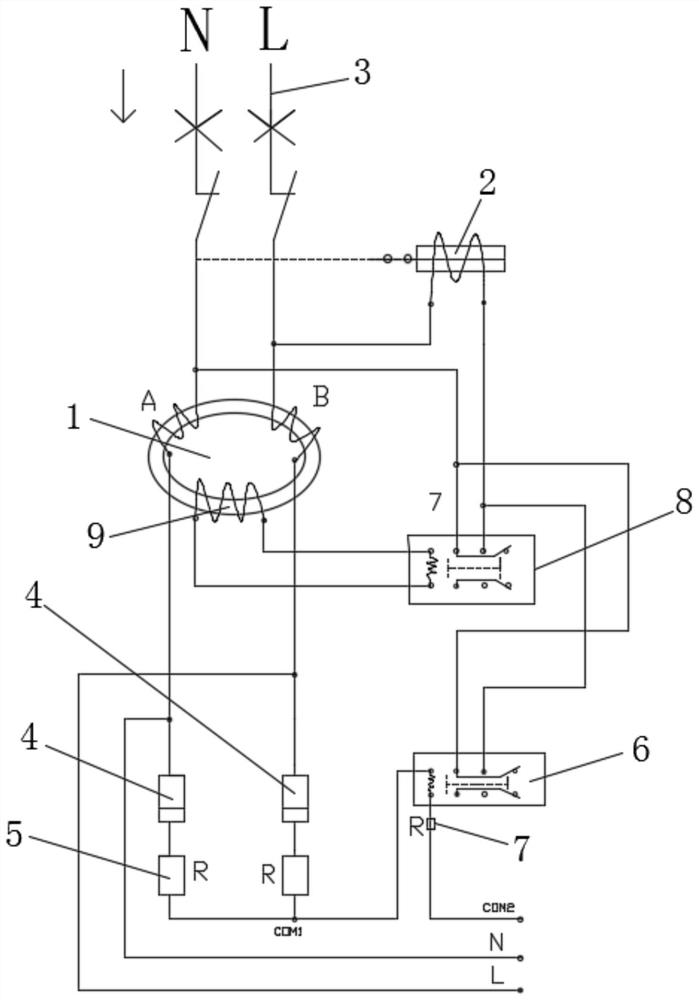
[0022] The embodiment of the present invention discloses a potential leakage protection system, such as figure 1 As shown, it includes neutral (N) wire, live (L) wire, closed magnetic flux 1, electromagnet 2 and circuit breaker 3. The first end of the neutral wire and the live wire are connected to the switch load end, and the second ends are connected After entering the unidirectional conductive tube 4, connect two precision resistors 5 from the output end of the unidirectional conductive tube 4. The unidirectional conductive tube 4 is a diode, and the ends of the two precision resistors 5 are merged to form the same polarity of the L line and the N line. The common terminal (COM1) is combined and connected to the input terminal of the first precision rel...


PUM


Abstract

The invention relates to the field of switch protection, and discloses a potential type electric leakage protection system, which comprises a zero line, a live wire, a closed magnetic flux, an electromagnet and a circuit breaker, and is characterized in that first ends of the zero line and the live wire are connected with a switch load end, and second ends are respectively connected to a unidirectional conductive tube and then are connected with a precision resistor from an output end of the unidirectional conductive tube; the precision resistor end connected with the zero line and the live line is connected with the input end of a first precision relay, the output end of the first precision relay is connected with a current-limiting resistor, and the tail end of the current-limiting resistor is connected with a ground wire, an electric appliance metal shell or a rack; the second ends of the live wire and the zero wire penetrate through the closed magnetic flux and then are connected with the circuit breaker switch, the closed magnetic flux is connected to the input end of the second relay, the output end of the second relay is connected with the first end of the electromagnet, thesecond end of the electromagnet is connected with the circuit breaker switch end, and the output end of the first relay is connected with the output end of the second relay. Potential safety hazardscaused by poor grounding and failure of the ground wire are effectively solved, and the power utilization environment is greener and safer.

Description

technical field [0001] The invention relates to the field of switch protection, in particular to a potential leakage protection system. Background technique [0002] In today's social civilization and the development of science and technology, in our daily life, various leakage protection switches provide us with effective and safe electricity protection, but there is a common shortcoming, that is, the neutral line is first in the process of using electricity. When the neutral line first contacts with the ground, there will be no corresponding circuit breaker action protection, and when the grounding state of the electrical appliance changes and is in a bad state (the electrical appliance is in an insulator or semi-insulator, and the grounding wire is disconnected), the live wire will not break the circuit when it comes into contact with it. Action break protection; however, this technology has the following disadvantages: [0003] 1. Even if the grounding is good in the po...

Claims


Application Information

Patent Timeline
Patent Type & Authority Applications(China)
IPC IPC(8): H02H3/34
CPCH02H3/34
Inventor 凌乔华杨文强
Owner 上海昱昌建设工程有限公司
Learn More