Multifunctional office table

A desk, multi-functional technology, applied in the field of furniture, can solve the problems of waste of space and single function, and achieve the effect of avoiding overcooling or overheating, soothing the human body, and improving the utilization rate.

Inactive Publication Date: 2020-11-20
CHONGQING MEDICAL & PHARMA COLLEGE
View PDF7 Cites 1 Cited by
  • Summary
  • Abstract
  • Description
  • Claims
  • Application Information

AI Technical Summary

Problems solved by technology

[0003] Existing desks can only be used to place items, and the function is relatively single. At the same time, because the current desks are basically designed in an inv

Method used


Image

  • Multifunctional office table
  • Multifunctional office table
  • Multifunctional office table

Examples


Embodiment 1

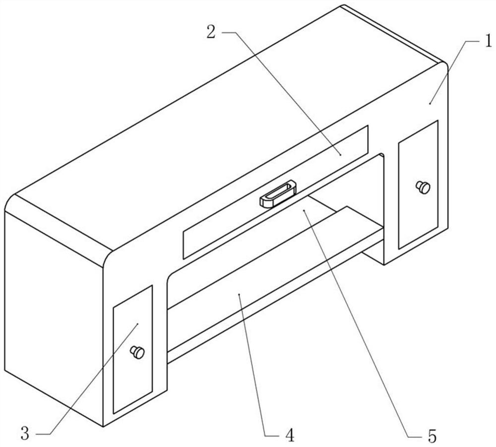
[0035] Basic as attached figure 1 As shown, a multifunctional desk includes a table body 1, a cavity is opened at the bottom of the table body 1, the whole table body 1 is in the shape of a "concave", an upper drawer 2 is arranged on the top of the table body 1, and an upper drawer 2 is arranged on the top of the table body 1. Side drawers 3 are arranged on both sides.

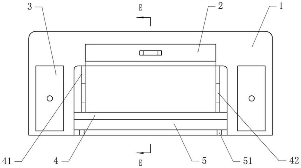
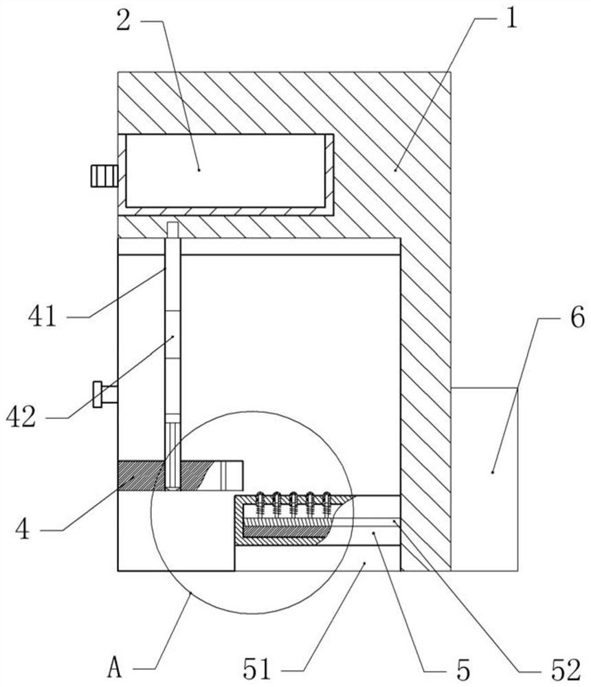
[0036] as attached figure 2 As shown, the cavity is provided with a pedal 4 and a rest bed positioned below the pedal 4, the two sides of the pedal 4 are provided with an adjustment shaft 41, and one side of the table body 1 is provided with a temperature adjustment mechanism 6, combined with the attached image 3 And attached Figure 4 As shown, the upper end of the adjustment shaft 41 is rotatably connected with the table body 1 , and the lower end of the adjustment shaft 41 is screwed with the pedal 4 . Both sides on the pedal 4 are bolted with a vertical second slide plate 43, and the two sides of the ...

Embodiment 2

[0045] The difference between embodiment two and embodiment one is that, as attached Figure 5 And attached Image 6 As shown, the pedal 4 is provided with an air cavity 44 and an exhaust hole 45 located below, and the exhaust hole 45 communicates with the air cavity 44 . Another cold air pipe 64 connected to the cold air end 63 communicates with the air chamber 44 , and another cold air pipe 64 connected to the hot air end 67 communicates with the air chamber 44 . Pedal 4 is positioned at the top of main body 5, and the upper surface of main body 5 is 3~6cm apart from the ground of pedal 4, and this embodiment is 5cm apart.

[0046] The specific implementation process is as follows:

[0047] Send certain cold air into the temperature chamber 53 in advance to store it up. At this time, because the reversing valve 65 and the hot air end 67 are blocked, the hot air enters the air chamber 44 through another hot air pipe 66 .

[0048] When the rest bed is pulled out, the rest b...


PUM


Abstract

The invention relates to the technical field of furniture, and discloses a multifunctional office table which comprises a table body, a cavity is formed in the lower portion of the table body, drawersare arranged on the upper portion and the two sides of the table body, a rest bed is horizontally connected into the cavity of the table body in a sliding mode, and a temperature adjusting mechanismis installed on the table body. The rest bed comprises a body and a temperature cavity formed in the body, the temperature cavity is communicated with the temperature adjusting mechanism, a pluralityof supporting shafts are fixed in the temperature cavity, and each supporting shaft is sleeved with a hollow massage sleeve which is vertically connected with the body in a sliding mode; a plurality of air holes communicated with the massage sleeve are formed in the upper portion of the massage sleeve, an elastic piece arranged on the supporting shaft in a sleeving mode is arranged on the lower portion of the massage sleeve, a plurality of communicating holes are formed in the side wall of the massage sleeve, and when the massage sleeve slides downwards into the temperature cavity, the massagesleeve is communicated with the temperature cavity through the communicating holes. The office table is simple in structure, the rest bed is integrated on the office table, the space of the table body is fully utilized, and the temperature adjusting mechanism is arranged to adjust the rest bed, so that an operator feels comfortable.

Description

technical field [0001] The invention relates to the technical field of furniture, in particular to a multifunctional desk. Background technique [0002] Desk refers to the desk that is equipped for the convenience of work in daily work and social activities. The existing desk includes a desk body and drawers on the desk body. The desk body is used to place documents and computers needed for office work. etc., drawers are used to store personal items or other office documents. [0003] Existing desks can only be used to place items, and the function is relatively single. At the same time, because the current desks are basically designed in an inverted "concave" shape, there is still a large space in the concave cavity of the desk. This space is wasted by placing the feet only for the person using the desk. In order to use the space reasonably, it is necessary to improve the desk to increase the utilization rate of the desk. Contents of the invention [0004] The present ...

Claims


Application Information

Patent Timeline
IPC IPC(8): A47B17/00A47B13/02A47B83/04A47C17/62A47C21/04A47C21/00A61H7/00A61H9/00A61F7/00B08B5/02
CPCA47B17/00A47B13/02A47B83/04A47C17/62A47C21/044A47C21/048A47C21/00A61H7/00A61H9/005A61F7/00B08B5/02A47B2200/0097A61H2201/0138A61H2201/0142A61H2201/0207A61H2201/0214A61H2201/025A61F2007/006A61F2007/0064
Inventor 何伟
Owner CHONGQING MEDICAL & PHARMA COLLEGE
Why Eureka
Try Eureka