Pelvic floor surgery puncture outfit for internal medicine operation

A trocar technique for surgery, applied to the field of pelvic floor surgery trocars for medical surgery, and can solve the problems of hand shaking and accidental injury to patients, etc.

Active Publication Date: 2020-11-20
高怀秀 +1
View PDF11 Cites 2 Cited by
  • Summary
  • Abstract
  • Description
  • Claims
  • Application Information

AI Technical Summary

Problems solved by technology

This invention needs to be held by hand to work. It is unavoidable that the hands will shake when performing puncture work for a long time, which may accidentally injure

Method used


Image

  • Pelvic floor surgery puncture outfit for internal medicine operation
  • Pelvic floor surgery puncture outfit for internal medicine operation
  • Pelvic floor surgery puncture outfit for internal medicine operation

Examples


specific Embodiment approach 1

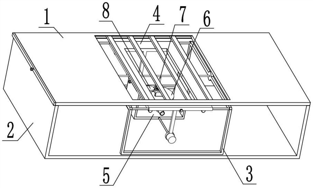
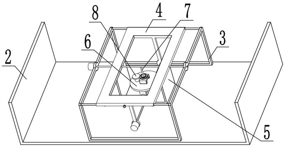
[0033] Combine below Figure 1-12This embodiment is described. The present invention relates to the technical field of medical equipment, more specifically, a pelvic floor puncture device for medical surgery, which includes a patient lying flat bed member 1, a support and fixing device 2, a limiting lateral movement device 3, a lateral Adjust the supporting device 4, the front and rear supporting carriage device 5, the elevating and supporting disc device 6, the puncture and suction device 7 and the rotating power device 8, and let the patient lie on the flat bed 1-1 and fix it. , use the motor I3-4 and the motor II4-7 to adjust the position of the puncture needle 7-4, so that the puncture needle 7-4 is in the correct puncture position, and use the three telescopic rods 5-3 to drive the puncture needle 7-4 to move upwards, Thereby inserted into the body of the patient, when running into muscle or other tissues that are difficult to puncture, the puncture needle 7-4 can be driv...

specific Embodiment approach 2

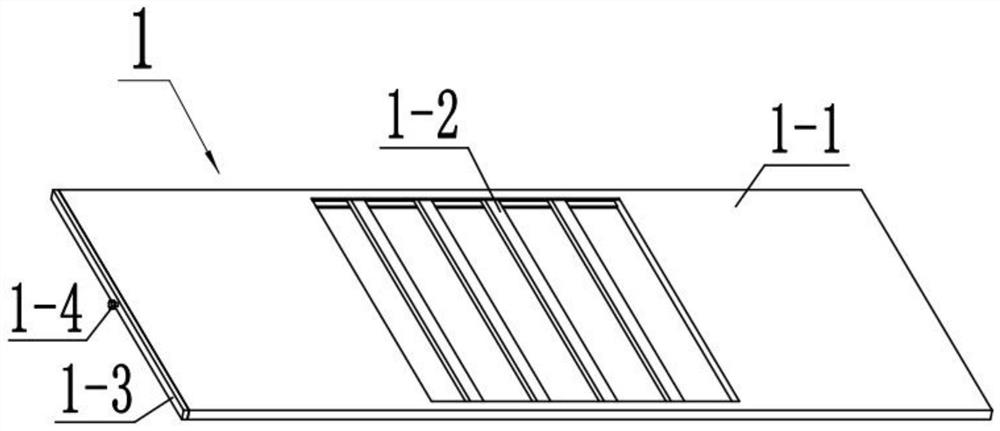
[0036] Combine below Figure 1-12 Describe this embodiment, this embodiment will further explain Embodiment 1. The patient lying flat bed board member 1 includes a flat lying board 1-1, a supporting carriage 1-2, a side vertical blocking board 1-3 and an adjustment screw 1 -4, a fixing device can be provided on the flat bed 1-1, which is convenient for fixing the patient. There is a sliding cavity inside the flat bed 1-1, and the sliding cavity can provide a sliding space for the supporting carriage 1-2, and support The sliding frame 1-2 is slidably connected in the sliding chamber on the flat bed 1-1, the supporting sliding frame 1-2 plays a supporting role, and the supporting sliding frame 1-2 is provided with multiple gaps, and the puncture needle 7-4 It can pass through multiple gaps on the support carriage 1-2, and when the support carriage 1-2 hinders the upward movement of the puncture needle 7-4, the adjustable lead screw 1-4 can be rotated to drive the support carriag...

specific Embodiment approach 3

[0038] Combine below Figure 1-12 Describe this embodiment mode. This embodiment mode will further explain Embodiment 2. The support and fixing device 2 includes a load-bearing bottom plate 2-1 and a support side plate 2-2. The universal wheel facilitates the movement of the device. The two ends above the load-bearing base plate 2-1 are fixedly connected with a support side plate 2-2. -1 provides a fixed space, and the lying board 1-1 is fixedly connected above the two supporting side boards 2-2.


PUM


Abstract

The invention relates to the technical field of medical equipment, in particular to a pelvic floor surgery puncture outfit for an internal medicine operation. The pelvic floor surgery puncture outfitcomprises a patient lying bed board component, a supporting and fixing device, a limiting transverse moving device, a transverse adjusting bearing device, a front and rear bearing sliding frame device, a lifting bearing disc device, a puncture liquid sucking device and a rotating power device, wherein the supporting and fixing device is fixedly connected to the lower portion of the patient lying bed board component, the limiting transverse moving device is fixedly connected to the supporting and fixing device, the transverse adjusting bearing device is connected to the limiting transverse moving device in a sliding mode, the front-back bearing sliding frame device is connected to the transverse adjusting bearing device in a sliding mode, and a lifting bearing disc device is fixedly connected to the front and rear bearing sliding frame device, and a puncture liquid sucking device is rotationally connected to the lifting bearing disc device. The device disclosed by the invention can accurately puncture and suck liquid for a patient without being held by a hand, so that the workload of a doctor is reduced.

Description

technical field [0001] The invention relates to the technical field of medical equipment, in particular to a pelvic floor operation trocar for medical operations. Background technique [0002] Now there is a pelvic floor trocar with the patent No. CN201810961269.4, which includes a top seat. The two sides of the top of the top seat are respectively provided with rectangular grooves, and the middle part of the inner back of the rectangular groove is hinged with a passive Buckle, the bottom end of one side of the passive buckle is fixedly connected with a return spring, the other end of the return spring is fixedly connected with one side inside the rectangular groove, and the bottom end of the other side of the passive buckle is fixedly connected with a L-shaped bar, the top of the L-shaped bar runs through and extends to the top of the rectangular slot, the inside of the rectangular slot is movably sleeved with an active buckle, and the active buckle is located on the side o...

Claims


Application Information

Patent Timeline
IPC IPC(8): A61B17/34
CPCA61B17/3403A61B17/3476A61B2217/005
Inventor 温培成
Owner 高怀秀
Why Eureka
Try Eureka