Composite no-clean dust removal device

A dust removal device and no-cleaning technology, applied in transportation and packaging, dispersed particle separation, chemical instruments and methods, etc., can solve the problems of complex structure of dust removal system, short maintenance period, and complex structure of analysis dust removal system.

Pending Publication Date: 2020-11-20
HUBEI UNIV OF SCI & TECH
View PDF0 Cites 3 Cited by
  • Summary
  • Abstract
  • Description
  • Claims
  • Application Information

AI Technical Summary

Problems solved by technology

[0002] Filtered exhaust gas dedusting is a commonly used high-efficiency dedusting method, but it has the characteristics of short maintenance period, and the filter structure (such as filter screen, filter bag, etc.) needs to be replaced or cleaned frequently according to the filtering situation.
As its deep-seated defect, its dust removal effect gradually weakens with the prolongation of the use time of the filter bag or filter screen. Therefore, in the dust removal system with higher requirements, the filter type dust removal is generally equipped with multiple stages, and the filter dust removal effect is gradually reduced by gradually reducing the dust removal effect. The filter holes are used to filter layer by layer to achieve better filtering effect and longer cleaning and maintenance cycle. In some cases, the filter type dust removal structure is only used as one of the links of the dust removal system, resulting in a complex structure of the dust removal system.
[0003] Analysis of the reason why the structure of the dust removal system is complex and the dust removal effect weakens with the passage of time is that the separation structure such as the filter screen cannot realize real-time reverse cleaning, so that the filter holes of the filter structure cannot be set too small, and it needs to be cleaned many times. Gradually reduce the filter holes in a gradual way to classify and screen the particles to be filtered. Based on this, this program improves and breaks through it

Method used


Image

  • Composite no-clean dust removal device
  • Composite no-clean dust removal device
  • Composite no-clean dust removal device

Examples


Embodiment Construction

[0026] The following are specific embodiments of the present invention and in conjunction with the accompanying drawings, the technical solutions of the present invention are further described, but the present invention is not limited to these embodiments.

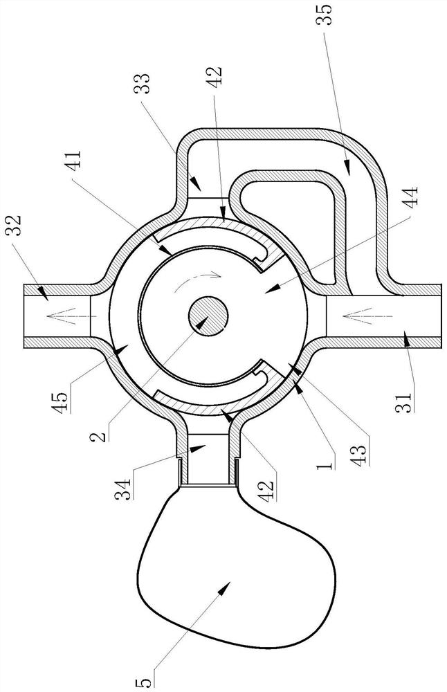
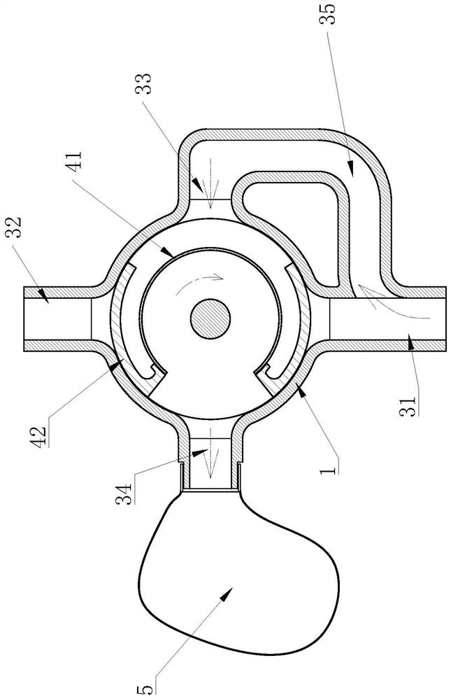
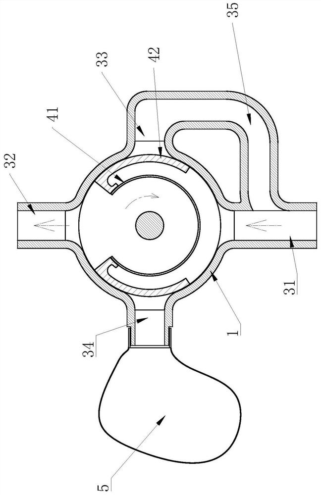
[0027] Such as figure 1 and Figure 5 As shown, it includes a tubular dust removal casing 1 and a rotating shaft 2 that is rotatably connected to the dust removal casing 1. The side wall of the dust removal casing 1 is connected with a main air intake pipe 31, a main exhaust pipe 32, an auxiliary air intake pipe 33 and an auxiliary exhaust pipe. 34. The main intake pipe 31, the main exhaust pipe 32, the auxiliary air intake pipe 33 and the auxiliary exhaust pipe 34 are evenly arranged on the outer side of the dust removal shell 1, and the main air intake pipe 31 and the main exhaust pipe 32 are on the same straight line. The auxiliary air intake pipe 33 communicates with the middle part of the main air intake pipe 31 thro...


PUM


Abstract

The invention provides a composite no-clean dust removal device, and belongs to the technical field of environmental protection equipment. The dust removal device comprises a tubular dust removal housing and a rotating shaft rotationally connected to the dust removal housing; a main air inlet pipe, a main air outlet pipe, an auxiliary air inlet pipe and an auxiliary air outlet pipe are connected to the side wall of the dust removal housing; the main air inlet pipe, the main air outlet pipe, the auxiliary air inlet pipe and the auxiliary air outlet pipe are circumferentially and uniformly arranged on the outer side of the dust removal housing; the main air inlet pipe and the main air outlet pipe are located on the same straight line, and the auxiliary air inlet pipe is communicated with themiddle of the main air inlet pipe through a bypass pipe; the air outlet end of the auxiliary air outlet pipe is connected with a filter bag; an arc-shaped filter screen with a first notch is fixedlyarranged on the rotating shaft, the arc-shaped angle of the filter screen ranges from 240 degrees to 340 degrees, and two arc-shaped baffles are arranged on the outer side of the filter screen; and the rotating shaft is connected with a driving mechanism capable of driving the rotating shaft to rotate. The device has the advantages of no need of cleaning the filter screen and the like.

Description

technical field [0001] The invention belongs to the technical field of environmental protection equipment, and relates to a composite non-cleaning dust removal device. Background technique [0002] Filtration exhaust gas dedusting is a commonly used high-efficiency dedusting method, but it has the characteristics of short maintenance period, and the filter structure (such as filter screen, filter bag, etc.) needs to be replaced or cleaned frequently according to the filtration situation. As its deep-seated defect, its dust removal effect gradually weakens with the prolongation of the use time of the filter bag or filter screen. Therefore, in the dust removal system with high requirements, the filter type dust removal is generally equipped with multiple stages, and the filter dust removal effect is gradually reduced by gradually reducing Filter holes are used to filter layer by layer to achieve better filtering effect and longer cleaning and maintenance cycle. In some cases, ...

Claims


Application Information

Patent Timeline
Patent Type & Authority Applications(China)
IPC IPC(8): B01D46/10B01D46/02B01D46/00
CPCB01D46/103B01D46/02B01D46/70
Inventor 曹慧刘宏章
Owner HUBEI UNIV OF SCI & TECH
Why Eureka
Try Eureka