Modular mounting method for electric precipitator shell
An installation method and technology of electrostatic precipitator, applied in electrode conveying device, electrostatic separation, human health protection and other directions, can solve the problems of increasing the overall height of the precipitator, deformation of the electrostatic precipitator, easy deformation, etc., to improve the dust removal effect, Guaranteed sealing performance and small workload
- Summary
- Abstract
- Description
- Claims
- Application Information
AI Technical Summary
Problems solved by technology
Method used
Image
Examples
Embodiment 1
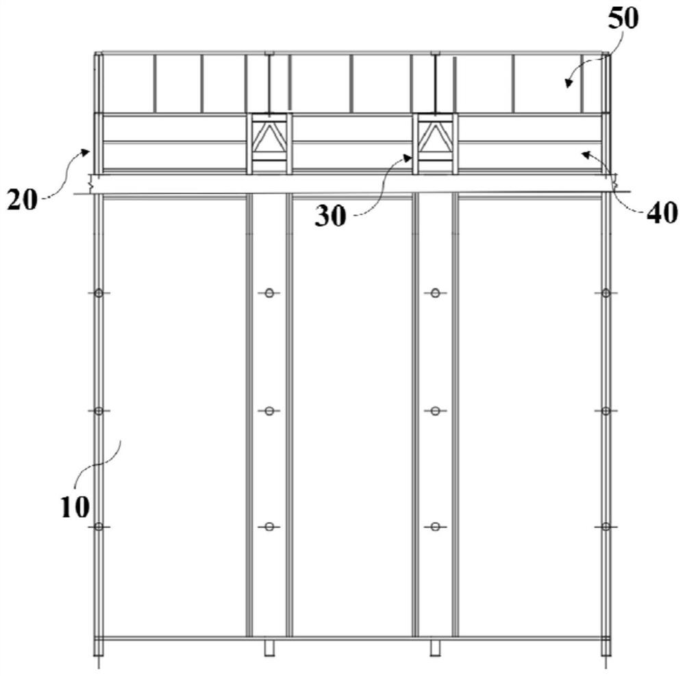
[0047] combine figure 1 and figure 2 , a modular installation method of an electrostatic precipitator shell in this embodiment is modified on the basis of the original precipitator 10, and its structure includes a first support unit 20, a second Two supporting units 30 , side plates 40 and upper beams 50 , wherein the first supporting unit 20 and the second supporting unit 30 are used as main supporting components during transformation, so as to ensure the stability of the modified electrostatic precipitator. The first support unit 20 and the second support unit 30 in this embodiment are provided in multiples, the first support unit 20 is arranged along the circumference of the original dust collector 10, and the second support unit 30 is arranged on the original dust collector 10's interior.
[0048] A kind of modular installation method of electrostatic precipitator shell of this embodiment, its process is:
[0049] After removing the top equipment, top plate and pole pl...
Embodiment 2
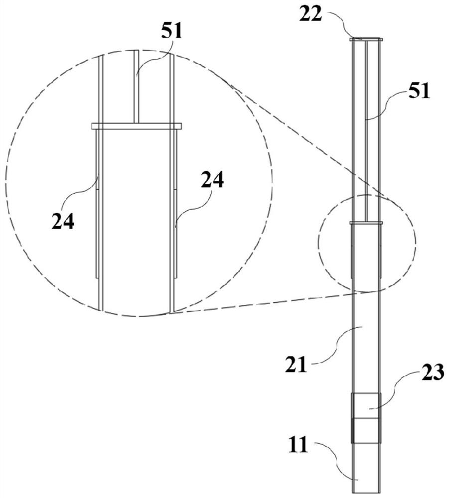
[0059] A modular installation method for an electrostatic precipitator housing in this embodiment is basically the same as in Embodiment 1, further: combining image 3 and Figure 4 , the first support unit 20 in this embodiment includes a first support rod 21, a first reinforcement plate 23 and a support plate 24, wherein the first support rod 21 is connected to the original column 11 on the original dust collector 10, and the The first reinforcement plate 23 is arranged at the connection between the first support rod 21 and the original column 11, and the first reinforcement plate 23 is welded to the first support rod 21 and the original column 11. Reinforcement is carried out to ensure the sealing performance; the support plate 24 of this embodiment is arranged on the first support rod 21, and the installation direction of the support plate 24 is towards the inside of the original dust collector 10, such as Figure 4 As shown, the subsequent installation of the upper beam ...
Embodiment 3
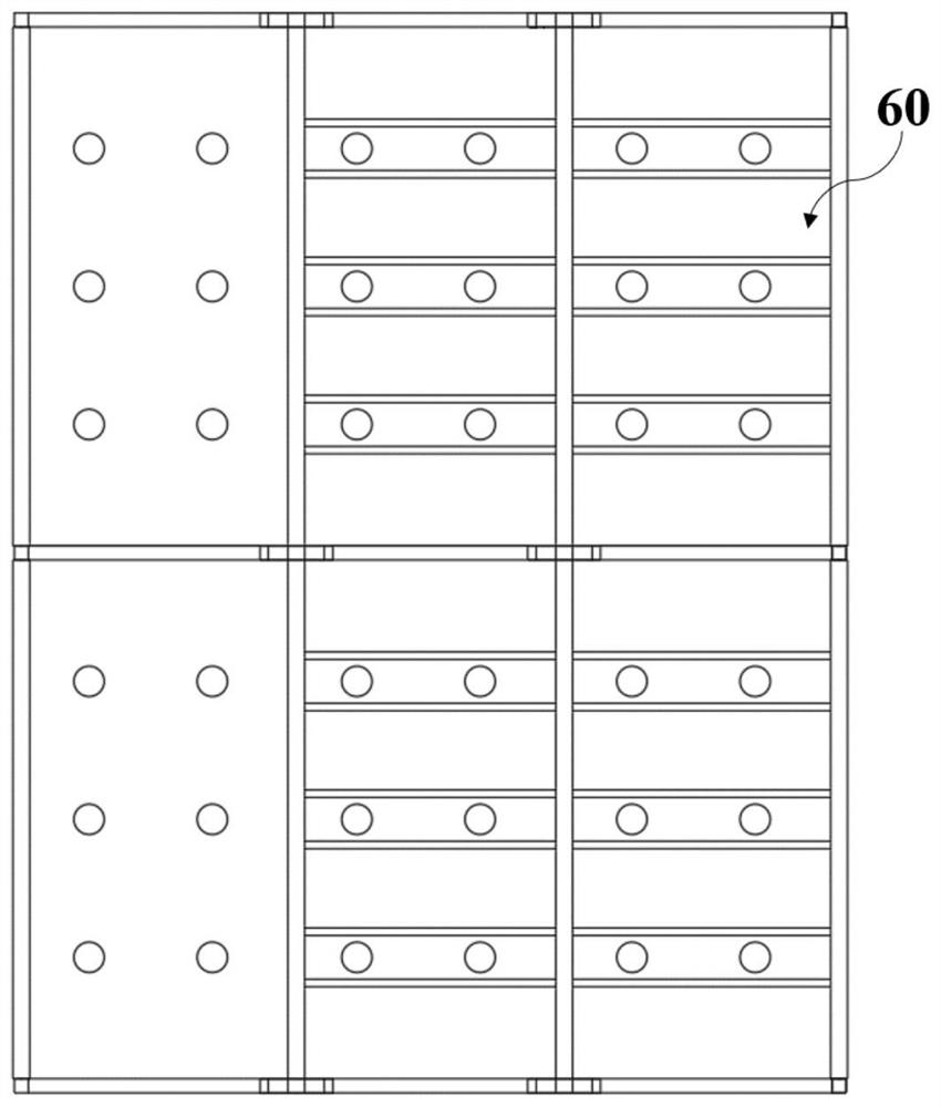
[0079] A modular installation method for an electrostatic precipitator housing in this embodiment is basically the same as in Embodiment 2, further: combining Figure 9 and Figure 10 In this embodiment, the top cover plate 60 is divided into several split modules according to the center size of the top frame beam of the electrostatic precipitator housing, and each split module includes an upper bottom plate 61, a lower bottom plate 62, channel steel 63, rock wool Plate 64 and flat steel 65, wherein, the upper bottom plate 61, the lower bottom plate 62 and the channel steel 63 form a frame structure, and the channel steel 63 is arranged along the circumferential direction of the upper bottom plate 61 and the lower bottom plate 62, that is, through the channel steel 63 For edge sealing, the channel steel 63 in this embodiment is fixedly connected to the upper bottom plate 61 and the lower bottom plate 62 in the form of full welding. The rock wool board 64 is arranged between t...
PUM
 Abstract
Description
Claims
Application Information
 - R&D
- Intellectual Property
- Life Sciences
- Materials
- Tech Scout
- Unparalleled Data Quality
- Higher Quality Content
- 60% Fewer Hallucinations
Browse by: Latest US Patents, China's latest patents, Technical Efficacy Thesaurus, Application Domain, Technology Topic, Popular Technical Reports.
© 2025 PatSnap. All rights reserved.Legal|Privacy policy|Modern Slavery Act Transparency Statement|Sitemap|About US| Contact US: help@patsnap.com


