Main shaft of numerical control machine tool and main shaft box thereof

A technology of CNC machine tools and spindle boxes, applied in the field of CNC machine tools, can solve problems such as poor convenience and inability to realize independent feeding of tools, and achieve the effects of avoiding jamming, realizing non-stop switching, and ensuring efficient oil injection.

Inactive Publication Date: 2020-11-20
台州松普数控科技有限公司
View PDF9 Cites 2 Cited by
  • Summary
  • Abstract
  • Description
  • Claims
  • Application Information

AI Technical Summary

Problems solved by technology

However, the above-mentioned spindle can only realize the control of the rotation of the tool in the circumferential direction, and cannot realize the independent feed of the tool. Therefore, when it is necessary to realize the feed of the tool, it can only drive the entire spindle to move and feed synchronously, which has the disadvantage of poor convenience and needs to be improved.

Method used


Image

  • Main shaft of numerical control machine tool and main shaft box thereof
  • Main shaft of numerical control machine tool and main shaft box thereof
  • Main shaft of numerical control machine tool and main shaft box thereof

Examples


Embodiment 1

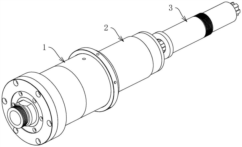
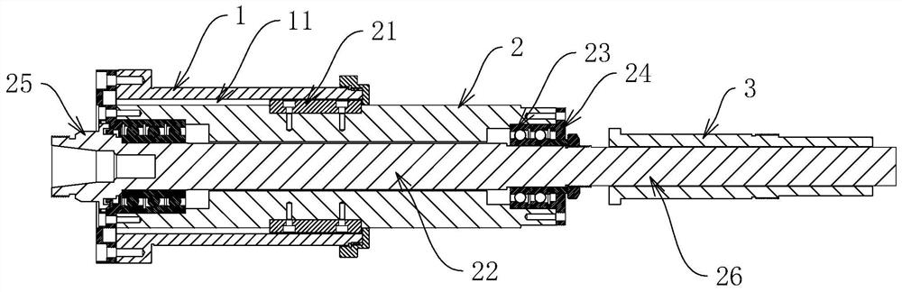
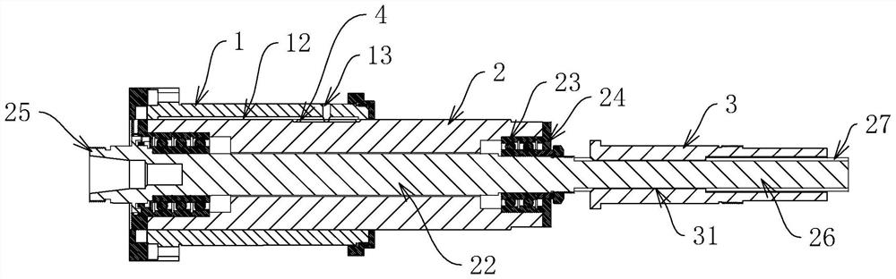
[0044] like figure 1 , figure 2 As shown, a spindle of a CNC machine tool includes a horizontally arranged shaft sleeve 1, and a mounting shaft 2 is horizontally slidably connected in the shaft sleeve 1. Both outer walls of the mounting shaft 2 are provided with guide blocks 21 horizontally, and both inner walls of the shaft sleeve 1 are provided with guide grooves 11 for horizontal sliding of the guide blocks 21 .

[0045] like figure 2 , image 3 As shown, a mandrel 22 is horizontally rotatably connected in the mounting shaft 2 , and a sealed bearing 23 and an end cover 24 covering the sealed bearing 23 are provided between the mandrel 22 and both ends of the mounting shaft 2 .

[0046] like figure 2 , image 3 As shown, one end of the mandrel 22 outside the installation shaft 2 is provided with a tool seat 25 for fixing the tool, and the other end outside the installation shaft 2 is extended with a sliding shaft 26 .

[0047] like figure 2 , image 3 As shown, t...

Embodiment 2

[0060] like Figure 5 As shown, a headstock of a CNC machine tool is used for installing the above-mentioned main shaft, and it comprises a base 5, and the base 5 is vertically and side by side provided with a front main board 6 and a rear main board 7, and the surrounding of the front main board 6 and the rear main board 7 Connecting ribs 51 are provided at all positions.

[0061] like Figure 5 , Image 6 As shown, a plurality of rows of front mounting hole groups 61 are arranged through the front main board 6 , and each row of front mounting hole groups 61 includes a plurality of front holes 62 arranged at intervals. The plurality of front holes 62 on the adjacent two rows of front mounting hole groups 61 are arranged in a staggered manner, and each front hole 62 is used for the shaft sleeve 1 (see figure 1 ) is embedded and fixed, and the shaft sleeve 1 is provided with a first retaining ring 14 fixed on the outer wall of the front main board 6 .

[0062] like Figure...


PUM


Abstract

The invention discloses a main shaft of a numerical control machine tool, and relates to the field of numerical control machine tools. The main shaft comprises a shaft sleeve, wherein a mounting shaftis horizontally and slidably connected in the shaft sleeve; a mandrel is horizontally and rotatably connected in the mounting shaft; end covers are arranged between the mandrel and the two ends of the mounting shaft; a tool apron used for fixing a tool is arranged at the end, positioned outside the mounting shaft, of the mandrel; a sliding shaft is arranged at the other end, positioned outside the mounting shaft, of the mandrel in an extending mode; a driving shaft is arranged on the outer wall of the sliding shaft; the sliding shaft is horizontally and slidably connected to the driving shaft; a spline is arranged on the outer wall of the sliding shaft; and a key groove allowing the spline to slide is formed in the inner wall of the driving shaft. The main shaft has the following advantages and effects that the mandrel and the sliding shaft which slide and rotate independently are arranged, the whole main shaft does not need to be driven to move synchronously for feeding, free feedingcontrol during rotation of the tool apron and the tool can be realized, and the use convenience of the main shaft is improved.

Description

technical field [0001] The present application relates to the field of CNC machine tools, and in particular, to a spindle of a CNC machine tool and a spindle box thereof. Background technique [0002] The spindle part of a CNC machine tool refers to the shaft on the machine tool that drives the workpiece or tool to rotate. It is usually composed of a spindle, a bearing and a transmission part. It is mainly used in the machine to support the transmission parts and transmit motion and torque. [0003] Chinese patent CN210412573U discloses a CNC machine tool spindle, which includes a clamping device and a shaft assembly. The shaft assembly includes a front end cover, a bearing seat, a shaft core, a rear end cover, a pulley and two bearing groups. The two bearing groups The spacer is sleeved on the shaft core, the bearing seat is arranged outside the two bearing groups, and a front end cover and a rear end cover are respectively detachably arranged at the front and rear. [000...

Claims


Application Information

Patent Timeline
Patent Type & Authority Applications(China)
IPC IPC(8): B23B19/02B23B19/00
CPCB23Q1/70
Inventor 储召发
Owner 台州松普数控科技有限公司
Why Eureka
Try Eureka