Part grinding device

A technology for parts and grinding heads, which is applied to grinding drive devices, abrasive surface adjustment devices, grinding/polishing safety devices, etc., and can solve problems affecting processing and gear blank deformation.

Inactive Publication Date: 2020-11-20
CHONGQING RUNYUE MACHINERY CO LTD
View PDF2 Cites 3 Cited by
  • Summary
  • Abstract
  • Description
  • Claims
  • Application Information

AI Technical Summary

Problems solved by technology

[0004] The present invention intends to provide a part grinding device to solve the problem that the grinding device in the prior art clamps and fixes the gear blank with a small thickness, which easily causes the deformation of the gear blank and affects the subsequent processing.

Method used


Image

  • Part grinding device
  • Part grinding device
  • Part grinding device

Examples


Embodiment 1

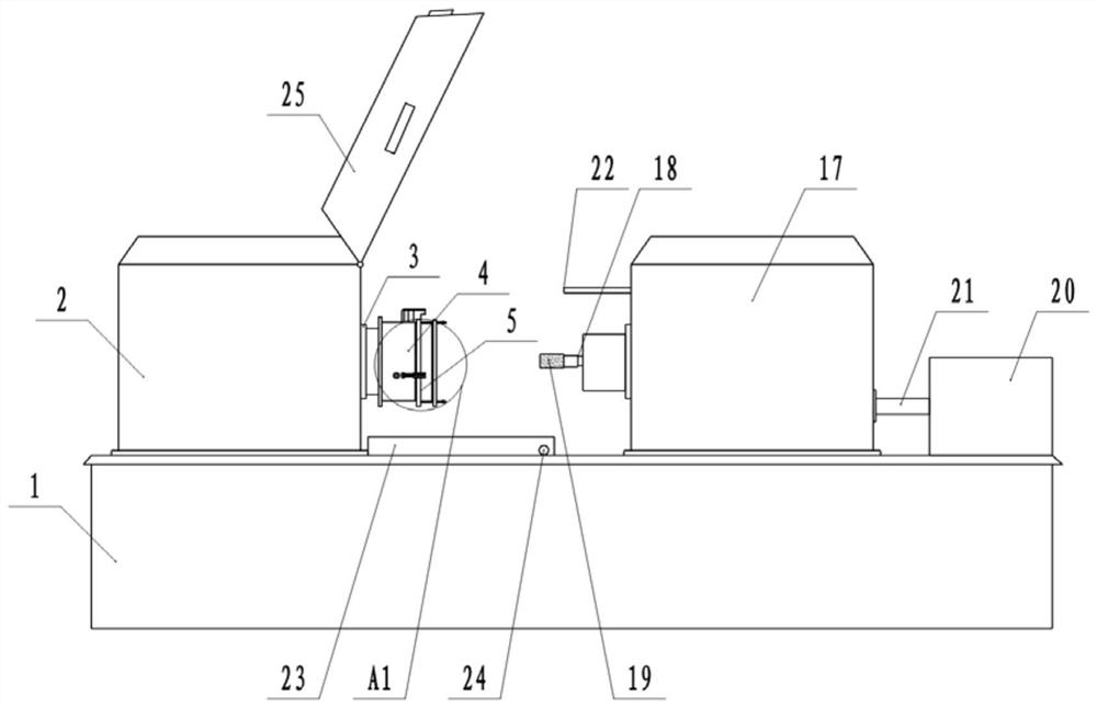
[0036] This embodiment is basically as attached figure 1 Shown: a parts grinding device, including a frame 1, a clamping mechanism, a grinding mechanism and a cleaning mechanism.

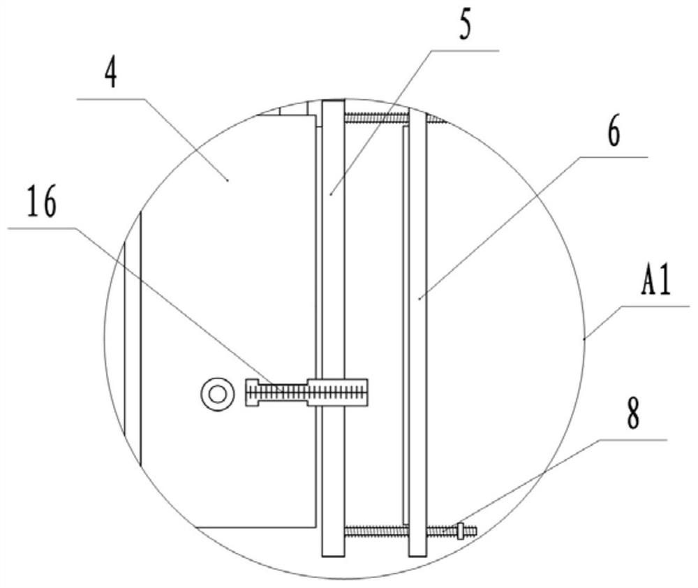
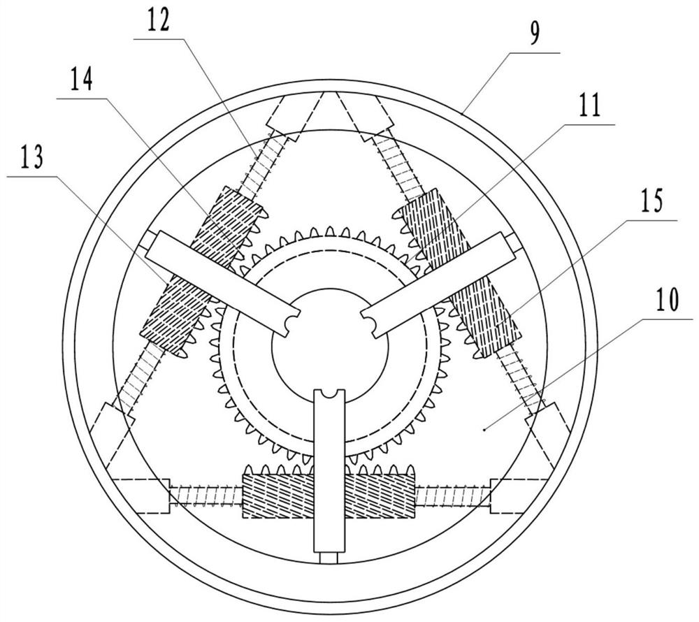
[0037] The frame 1 plays the role of supporting and ensuring the stable connection between the equipment. The clamping mechanism is used to clamp and fix the workpiece to be polished. The clamping mechanism includes the support platform 2 welded on the frame 1, and the right side of the support platform 2 A support disc 3 is fixedly connected to the wall, and the support disc 3 is rotatably connected with a clamping chuck 4, combined with Figure 3-Figure 5As shown, the clamping chuck 4 includes a chuck seat 9 and a chuck body 10, the chuck seat 9 is rotatably connected to the support plate 3, and the side of the chuck seat 9 away from the support plate 3 is coaxially fixed with a drive gear 11 , three threaded rods 12 are rotatably connected to the chuck seat 9, and the three threaded rods 12 are ...

Embodiment 2

[0046] like Figure 7 , Figure 8 As shown, the difference between this embodiment and Embodiment 1 is that in this embodiment, a correction mechanism is also provided on the frame 1, and the correction mechanism is used for grinding the outer surface of the polished grinding head 19 , to restore a certain roughness. The correction mechanism includes a slideway 26 fixedly connected to the frame 1. The slideway 26 is arranged across the front and rear ends of the frame 1. The slideway 26 is slidably connected with a correction base 27, and the correction base 27 is rotatably connected with a correction frame. 28, the top of the correction frame 28 is fixedly connected with a handwheel 29, and the bottom end of the correction frame 28 is rotatably connected with a correction head 30 that can face the grinding head 19.

[0047] In the process of using the grinding head 19 to grind the inner hole of the gear, since the force is mutual, as the equipment is used for a long time, t...


PUM


Abstract

The invention relates to the technical field of gear machining, and discloses a part grinding device. The part grinding device comprises a rack, wherein a clamping mechanism and a grinding mechanism are arranged on the rack; the clamping mechanism comprises a supporting table fixedly connected to the rack, a clamping chuck is rotationally connected to the supporting table, and an auxiliary clamping assembly is detachably connected to the clamping chuck; the auxiliary clamping assembly comprises a clamping disc with a round hole formed in the middle part, two clamping screws are arranged on theclamping disc, a pressing disc is connected between the two clamping screws, a grinding hole is formed in the middle part of the pressing disc, and the clamping screws are in threaded connection withlocking nuts; and the grinding mechanism comprises a supporting assembly connected to the rack in a sliding mode and a grinding head rotationally connected to the supporting assembly. The part grinding device solves the problems that subsequent machining is affected due to the fact that a gear blank is prone to deform when a grinding device clamps and fixes the thin-thickness gear blank in the prior art.

Description

technical field [0001] The invention relates to the technical field of gear processing, in particular to a parts grinding device. Background technique [0002] Gears are the core transmission components in automobile sports. The quality of their processing will have a direct impact on the vibration, noise and reliability of the automobile assembly and even the entire vehicle, and even become a key factor restricting the improvement of product quality. The processing process of gears usually includes forging blanks, normalizing, turning, rolling, gear shaping, shaving, heat treatment and other processes. Before the rolling and gear shaping processes, the forged blank needs to be processed in the middle by punching. , after the punching is completed, in order to make the perpendicularity between the inner hole and the end surface and the smoothness of the inner hole meet the processing accuracy requirements, the inner hole needs to be polished. [0003] At present, the grindi...

Claims


Application Information

Patent Timeline
Patent Type & Authority Applications(China)
IPC IPC(8): B24B5/48B24B41/06B24B55/06B24B41/02B24B47/06B24B47/12B24B55/02B24B55/00B24B53/075
CPCB24B5/48B24B41/067B24B55/06B24B41/02B24B47/06B24B47/12B24B55/02B24B55/00B24B53/075
Inventor 曾义杰
Owner CHONGQING RUNYUE MACHINERY CO LTD
Why Eureka
Try Eureka