Shot blasting machining method for hard rock cutter ring of shield tunneling machine

A processing method and shot blasting technology, applied in metal processing equipment, spray guns, manufacturing tools, etc., can solve the problems of shortening the life of hard rock cutter rings, deformation of thin blades, etc.

Pending Publication Date: 2020-11-20
JIANGSU UNIV
View PDF7 Cites 0 Cited by
  • Summary
  • Abstract
  • Description
  • Claims
  • Application Information

AI Technical Summary

Problems solved by technology

The traditional shot peening technology is easy to deform the thin blade and change the stress direction of the cutter ring, which will shorten the tunneling life of

Method used


Image

  • Shot blasting machining method for hard rock cutter ring of shield tunneling machine

Examples


Embodiment 1

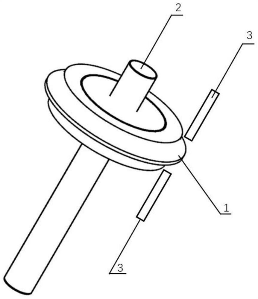
[0036] Fix the hard rock cutter ring on the rotating shaft according to the coincidence of the central axis of the hard rock cutter ring with the central axis of the rotating shaft;

[0037] A 1212P shot blasting machine is used to shot peen the blade of the hard rock knife ring. The shot peening conditions are as follows: the diameter of the knife ring is 17in, and the rotating shaft rotates around the axis at a speed of 10rpm; A 14mm spray gun is used to shot peen the blade area of ​​the hard rock cutter ring of the shield machine (the position extending 28mm from the edge boundary) using the runner injection method, wherein the injection incident angle is 80°, and the shot peening intensity is 0.09A·mm , the shot-peening pressure is 0.4MPa, the shot-peening coverage is 100%, and the spraying time is 7 minutes; the shot-peening shot is cast steel shot with a hardness of 52HRC.

Embodiment 2

[0044] Fix the hard rock cutter ring on the rotating shaft according to the coincidence of the central axis of the hard rock cutter ring with the central axis of the rotating shaft;

[0045] Use 1212P shot blasting machine to blast the blade of hard rock cutter ring. The shot blasting conditions are as follows: the diameter of the cutter ring is 19in, and the rotating shaft rotates around the axis at a speed of 13rpm; A 15mm spray gun is used to shot peen the edge area of ​​the hard rock cutter ring of the shield machine (the position extending 30mm from the edge boundary) using the flow channel injection method, wherein the injection incident angle is 90°, and the shot peening intensity is 0.10A mm. The shot-peening pressure is 0.5MPa, the shot-peening coverage is 120%, and the shot-peening time is 8 minutes; the shot-peening shot is cast steel shot with a hardness of 50HRC.

[0046] According to the test method of Example 1, the hard rock cutter ring in Example 2 is tested. ...

Embodiment 3

[0048] Fix the hard rock cutter ring on the rotating shaft according to the coincidence of the central axis of the hard rock cutter ring with the central axis of the rotating shaft;

[0049] Use 1212P shot blasting machine to shot peen the blade of hard rock cutter ring. The shot peening conditions are: the diameter of the cutter ring is 17in, and the rotating shaft rotates around the axis at a speed of 15rpm; A 16mm spray gun is used to shot peen the edge area of ​​the hard rock cutter ring of the shield machine (the position extending 32mm from the edge boundary) using the runner injection method, wherein the injection incident angle is 100°, and the shot peening intensity is 0.11A mm. The shot peening pressure is 0.6MPa, the shot peening coverage rate is 150%, and the shot time is 9 minutes; the shot peening shot is cast steel shot with a hardness of 48HRC.

[0050] The hard rock cutter ring in embodiment 3 is tested according to the test method of embodiment 1. After the s...


PUM

PropertyMeasurementUnit
Roughnessaaaaaaaaaa
Roughnessaaaaaaaaaa
Roughnessaaaaaaaaaa

Abstract

The invention belongs to the technical field of shield tunneling machine cutters, and particularly relates to a shot blasting machining method for a hard rock cutter ring of a shield tunneling machine. The shot blasting machining method for the hard rock cutter ring of the shield tunneling machine comprises the following steps that the hard rock cutter ring is fixed to a rotating shaft according to the coincidence of the central axis of the hard rock cutter ring and the central axis of the rotating shaft; spray gun nozzles are fixed, and shot blasting is conducted on the cutting edge area of the fixed hard rock cutter ring; the spray gun nozzles are symmetrically arranged on the front face and the back face of a cutting edge of the hard rock cutter ring; and in the shot blasting process, the relative displacement rate of the nozzles and the surface of the cutting edge of the hard rock cutter ring is 20-34cm/s, the diameter of the spray gun nozzles is 14-16mm, the distance between the spray gun nozzles and the cutting edge of the hard rock cutter ring is 90-110mm, the injection incidence angle is 80-100 degrees, and the shot blasting pressure is 0.4-0.6MPa. According to the shot blasting process, all the steps are in synergistic interaction, and the strengthening treatment effect of shot blasting machining on the hard rock cutter ring of the shield tunneling machine is greatly improved.

Description

technical field [0001] The invention belongs to the technical field of shield machine cutters, and in particular relates to a shot blasting processing method for a hard rock cutter ring of a shield machine. Background technique [0002] The shield machine is a super-large mechanical equipment dedicated to the excavation of hard rock formations. The cutter head of the shield machine is neatly equipped with replaceable disc-shaped hobs. Through the rotation and advancement of the cutter head, the rocks are broken and peeled off by the rolling and impact of the outermost cutter ring of the hob, and then gradually penetrate the tunnel. Under hard rock geological conditions, due to the severe impact and wear of the cutter ring during the working process, coupled with the inherent difficulty in matching the strength and toughness of the metal material, the cutter ring is extremely prone to failure. [0003] At present, the surface strengthening of the cutter ring of the mainstrea...

Claims


Application Information

Patent Timeline
IPC IPC(8): B24C1/10B24C5/04B24C7/00
CPCB24C1/10B24C5/04B24C7/0061
Inventor 袁志钟袁飞张琰琳曹赟罗锐张伯承程晓农
Owner JIANGSU UNIV
Why Eureka
Try Eureka