Slicing device for wood block

A technology for slicing devices and wood blocks, which can be used in wood processing equipment, forming/shaping machines, manufacturing tools, etc., and can solve problems such as errors

Active Publication Date: 2020-11-20
ZHEJIANG ZHENYANG COLD INSULATION TECH CO LTD
View PDF14 Cites 5 Cited by
  • Summary
  • Abstract
  • Description
  • Claims
  • Application Information

AI Technical Summary

Problems solved by technology

[0005] In order to overcome the shortcomings of manual slicing of wood blocks and errors in manual slicing, the technical problem to

Method used


Image

  • Slicing device for wood block
  • Slicing device for wood block
  • Slicing device for wood block

Examples


Embodiment 1

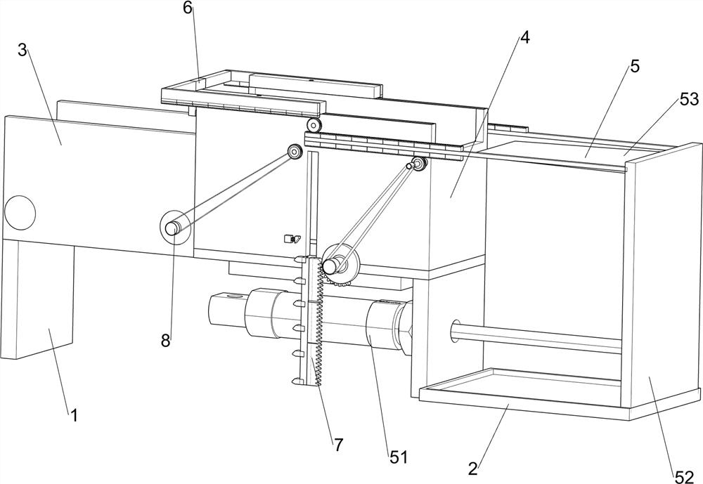
[0024] A device for slicing wood blocks, such as Figure 1-5 and Figure 8-9 As shown, it includes a support plate 1, a sliding frame 2, a mounting plate 3, a discharge box 4, a cutting mechanism 5 and a push-out mechanism 6, and the front and rear sides of the left side of the discharge box 4 are connected with a mounting plate 3, two The left side of mounting plate 3 bottoms is connected with support plate 1, and the right side of discharge box 4 bottoms is also connected with support plate 1, and the right side lower part of right support plate 1 is connected with slide frame 2, and on slide frame 2 A cutting mechanism 5 is provided, and a push-out mechanism 6 is arranged on the discharge box 4, and the push-out mechanism 6 is connected with the cutting mechanism 5 through transmission.

[0025] The cutting mechanism 5 includes a cylinder 51, a connecting slide 52 and a cutter 53, the top of the sliding frame 2 is slidably connected with a connecting slide 52, the upper le...

Embodiment 2

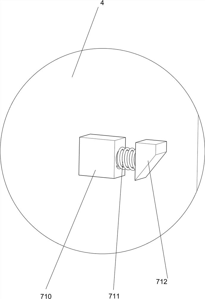
[0029] On the basis of Example 1, such as Figure 5-7 As shown, it also includes a lifting mechanism 7, and the lifting mechanism 7 includes a second rack 71, a second transmission rod 72, a first one-way gear 73, a first belt transmission group 74, a third transmission rod 75, and a half gear 76. , the third rack 77, the second wedge block 78, the push plate 79, the connecting block 710, the second spring 711 and the third wedge block 712, the bottom of the left side of the first transmission rod 61 on the front side is connected with the second rack 71 , the front side of the discharge box 4 on the lower side of the second rack 71 is rotatably connected with a second transmission rod 72, and the second transmission rod 72 is connected with a first one-way gear 73, and the first one-way gear 73 is connected to the second gear The bar 71 is engaged, and the front side of the discharge box 4 on the lower left side of the second transmission rod 72 is rotatably connected with a ...

Embodiment 3

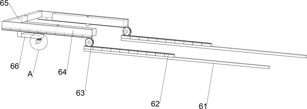
[0032] On the basis of Example 2, such as Figure 8-9 As shown, transport mechanism 8 is also included, and transport mechanism 8 includes second one-way gear 81, second belt transmission group 82, fourth transmission rod 83, roller 84 and conveyer belt 85, front side pinion 63 bottom left The front side of the discharge box 4 is rotatably connected with a second one-way gear 81, the second one-way gear 81 meshes with the second rack 71, and two fourth transmission gears are rotatably connected between the inner sides of the two mounting plates 3. Rod 83, two fourth transmission rods 83 are symmetrical left and right, the fourth transmission rod 83 is connected with a roller 84, is connected with a conveyor belt 85 between the two rollers 84, the right fourth transmission rod 83 and the second one-way gear 81 A second belt drive group 82 is connected between the drive shafts.

[0033] Chips move to the left and fall on the conveyor belt 85 thereupon, the second tooth bar 71 m...


PUM


Abstract

The invention relates to a slicing device, particularly relates to a slicing device for the wood block. According to the slicing device for the wood block, the wood block can be sliced without manpower and the wood block can be sliced uniformly. The slicing device for the wood block comprises a material placement box of which one side is connected with two mounting plates; supporting plates, wherein a supporting plate is connected with end parts of the mounting plates, and another supporting plate is also connected with the bottom of the material placement box; a sliding frame which is connected with one side of a supporting plate; a cutting mechanism which is set on the sliding frame; and a push-out mechanism which is set on the material placement box, wherein the push-out mechanism is indrive connection with the cutting mechanism. According to the device, through utilization of a lifting mechanism, the wood block can be moved upward; through utilization of the cutting mechanism, thewood block is sliced; through utilization of the push-out mechanism, wood chips are pushed out from the material placement box, so the wood chips fall on a conveying mechanism.

Description

technical field [0001] The invention relates to a slicing device, in particular to a slicing device for wood blocks. Background technique [0002] At present, the slicing of wooden blocks is generally done manually. The worker fixes the wooden block with one hand, and then slices the wooden block with a cutting machine with the other hand. This way, the workload of the workers is relatively large, and the workers rely on their senses to cut the wooden blocks. Slicing, the thickness of the cut wood chips is uneven, there are errors, and the workers hold the cutting machine for a long time to slice the wood blocks, and the arms are prone to soreness, which will reduce the efficiency of slicing. [0003] Therefore urgently need to develop a kind of cutting device for wood block that does not need to manually slice wood block and can slice wood block evenly. Contents of the invention [0004] (1) Technical problems to be solved [0005] In order to overcome the shortcomings ...

Claims


Application Information

Patent Timeline
IPC IPC(8): B27C5/02B27C5/06
CPCB27C5/02B27C5/06
Inventor 赵三秀
Owner ZHEJIANG ZHENYANG COLD INSULATION TECH CO LTD
Why Eureka
Try Eureka