New energy motor shell hot press mounting equipment

A motor housing and new energy technology, applied to household components, flat products, household appliances, etc., to achieve the effects of preventing damage, improving the quality of hot pressing, and improving the efficiency of hot pressing

Inactive Publication Date: 2020-11-20
巢湖宜安云海科技有限公司
View PDF8 Cites 1 Cited by
  • Summary
  • Abstract
  • Description
  • Claims
  • Application Information

AI Technical Summary

Problems solved by technology

[0004] The purpose of the present invention is: in order to solve the problem that the new energy motor housing thermal pressing equipment is not easy to fall off, the proposed new energy motor housing thermal pressing equipment

Method used


Image

  • New energy motor shell hot press mounting equipment
  • New energy motor shell hot press mounting equipment
  • New energy motor shell hot press mounting equipment

Examples


Embodiment 1

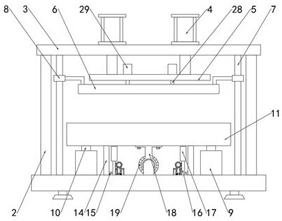
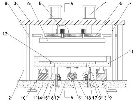
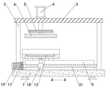
[0034] see Figure 1-5 , new energy motor housing thermal press assembly equipment, including a base 1, the upper end of the base 1 is provided with a column 2, the top of the column 2 is provided with a top plate 3, and the upper end of the base 1 is provided with symmetrically distributed guide rails 9, guide rails 9 Slider-10 is slidingly connected inside the slider-10, and the upper end surface of slider-10 is provided with a lower die 11, and the center of the lower end face of the lower die 11 is provided with a nut pair 18, and the inside of the nut pair 18 is screwed and connected with a screw 31. The end of the lead screw 31 is connected to the drive motor-19 installed on the base 1, the top plate 3 is provided with a cylinder 4, the telescopic end of the cylinder 4 is provided with a base plate 5, and the base plate 5 is connected with an upper platen 6 through a fixed rod 28 , the inside of the lower die 11 is embedded with a movable plate 12, the upper end surface ...

Embodiment 2

[0036] see Figure 1-5 , new energy motor housing thermal press assembly equipment, including a base 1, the upper end of the base 1 is provided with a column 2, the top of the column 2 is provided with a top plate 3, and the upper end of the base 1 is provided with symmetrically distributed guide rails 9, guide rails 9 Slider 10 is slidingly connected inside the slider 10, and the upper end surface of slider 10 is provided with a lower die 11, and the center of the lower end face of the lower die 11 is provided with a nut pair 18, and the inside of the nut pair 18 is screwed and connected with a screw 31. The end of the lead screw 31 is connected to the driving motor-19 installed on the base 1, the top plate 3 is provided with a cylinder 4, the telescopic end of the cylinder 4 is provided with a base plate 5, and the base plate 5 is connected with an upper platen 6 through a fixed rod 28 , the bottom of the fixed rod 28 is fixedly connected with the upper pressing plate 6, the...

Embodiment 3

[0038] see Figure 1-5, new energy motor housing thermal press assembly equipment, including a base 1, the upper end of the base 1 is provided with a column 2, the top of the column 2 is provided with a top plate 3, and the upper end of the base 1 is provided with symmetrically distributed guide rails 9, guide rails 9 Slider-10 is slidingly connected inside the slider-10, and the upper end surface of slider-10 is provided with a lower die 11, and the center of the lower end face of the lower die 11 is provided with a nut pair 18, and the inside of the nut pair 18 is screwed and connected with a screw 31. The end of the lead screw 31 is connected to the drive motor-19 installed on the base 1, the top plate 3 is provided with a cylinder 4, the telescopic end of the cylinder 4 is provided with a base plate 5, and the base plate 5 is connected with an upper platen 6 through a fixed rod 28 , the inside of the lower die 11 is embedded with a movable plate 12, the lower end surface o...


PUM


Abstract

The invention discloses new energy motor shell hot press mounting equipment, comprising a base, wherein vertical posts are set on the upper end face of the base, a top plate is set at the top ends ofthe vertical posts, symmetrically distributed guide rails are set on the upper end face of the base, and first sliding blocks are in sliding connection within the guide rails. According to the equipment, when the equipment is used, a to-be-processed motor shell is placed on a lower press mold. Cylinders are started. The cylinders drives a base plate to move downward. The base plate drives an upperpress plate to move downward through fixing rods, thereby carrying out hot press on the motor shell. The upper press plate drives sliding sleeves to slide downward out of sliding rods. When the upperpress plate contacts with the motor shell, under the effect of pressure, the upper press plate moves upward, the upper press plate drives the fixing rods to slide upward and first springs are compressed, so a buffering process exists in a downward press process of the upper press plate, the motor shell is prevented from being damaged due to excessive press force of the upper press plate, and thehot press quality of the new energy motor shell hot press mounting equipment is improved.

Description

technical field [0001] The invention relates to the technical field of hot pressing equipment, in particular to hot pressing equipment for housings of new energy motors. Background technique [0002] Hot pressing is the process of heating and pressing the paved and formed slabs to make fiberboards with certain mechanical strength and water resistance. Whether it is wet production of hard boards or semi-rigid boards, or dry production of hard boards Solid board or medium density board must be hot pressed to form a shaped board. [0003] The existing new energy motor housing hot pressing equipment is not easy to separate from the lower mold cavity after hot pressing, and it needs to be separated by manpower. The separation process is time-consuming and laborious, which reduces the separation of the new energy motor housing hot pressing equipment efficiency. Contents of the invention [0004] The purpose of the present invention is to solve the problem that the new energy m...

Claims


Application Information

Patent Timeline
Patent Type & Authority Applications(China)
IPC IPC(8): B27N3/04B27N3/08
CPCB27N3/04B27N3/08
Inventor 高兵熊明
Owner 巢湖宜安云海科技有限公司
Why Eureka
Try Eureka