
Blood collection needle injection mold and blood collection needle injection technology

A technology for injection molds and blood collection needles, which is applied in the direction of coating, etc., can solve the problems of increased pain and insufficient penetration into the skin, and achieve the effect of small incision, beautiful appearance and saving injection molding process steps

Pending Publication Date: 2020-11-20
HUAIAN TIANDA MEDICAL INSTR
View PDF0 Cites 1 Cited by
  • Summary
  • Abstract
  • Description
  • Claims
  • Application Information

AI Technical Summary

Problems solved by technology

[0004] Purpose of the invention: Aiming at the problems existing in the prior art, the present invention provides a blood collection needle injection mold and a blood collection needle injection molding process. The injection mold solves the problem of blood collection in injection molding in the prior art by modifying the position of the glue inlet and adjusting the direction of the glue inlet. The needle body is easy to move in the needle handle, resulting in insufficient penetration into the skin and increasing pain; and the injection molding process is carried out through the corresponding injection mold, reducing cutting, human inspection, counting and other corresponding injection molding process steps, saving costs

Method used


Image

  • Blood collection needle injection mold and blood collection needle injection technology
  • Blood collection needle injection mold and blood collection needle injection technology
  • Blood collection needle injection mold and blood collection needle injection technology

Examples


Embodiment Construction

[0031] The present invention will be further described with reference to the accompanying drawings. The following examples are only used to illustrate the technical scheme of the present invention more clearly, but not to limit the scope of protection of the present invention.

[0032] In the description of the present invention, it should be understood that the terms center, longitudinal, transverse, upper, lower, front, rear, left, right, vertical, horizontal, top, bottom and inside

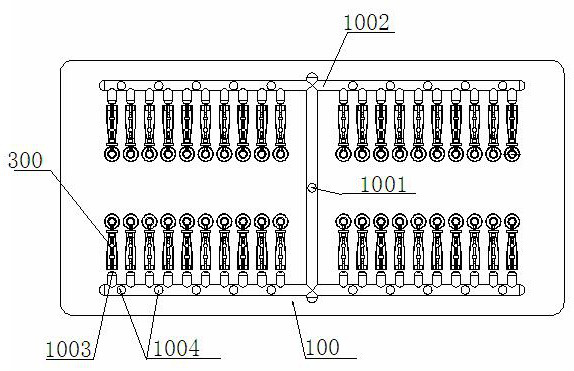
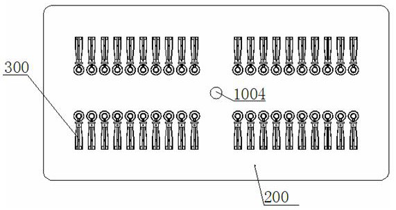
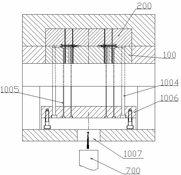
[0033] See attached Figure 1 The invention discloses an injection mold for a blood collection needle, which is formed by combining an upper mold 200 and a lower mold 100. The upper mold 200 and the lower mold 100 are provided with at least one corresponding mold cavity 300. In this embodiment, taking a plurality of mold cavities 300 as examples, each mold cavity 300 respectively includes a needle cap cavity 3001 and a needle handle cavity 3002 which are communicated with each other. The lower mold ...


PUM

PropertyMeasurementUnit
angleaaaaaaaaaa

Abstract

The invention relates to the technical field of blood collection needle production and discloses a blood collection needle injection mold and a blood collection needle injection technology. The injection mold is formed by folding an upper mold and a lower mold. At least one mutually corresponding mold cavity is set on the upper mold and the lower mold. Each mold cavity comprises a needle cap cavity and a needle handle cavity which are communicated. A gate and a main runner are set on the lower mold. The gate is communicated with the mold cavity. An injector nozzle communicated with the main runner is set on the upper mold. The gate is located at one end of the needle handle cavity away from the needle cap cavity. A preset included angle is formed between the gate and a plane where the tailend of the needle handle cavity is in. A connection point of the gate and the needle handle cavity deviates from a needle body. The injection technology comprises the steps of placing needles, folding the molds, injecting plastic and opening the molds. According to the injection mold and the injection technology, through modification of a gate location and through adjustment of a plastic injection direction, the problem that an injection molded blood collection needle body penetrates into skin insufficiently and pain is increased due to the fact that the injection molded blood collection needle body is liable to translate in a needle handle is solved. The injection technology is carried out through utilization of the corresponding injection molds, so injection technology steps such as cutting and manual checking are reduced, and the cost is reduced.

Description

Technical field [0001] The invention relates to the technical field of production of blood collection needles, in particular to an injection mold for blood collection needles and an injection process thereof. technical background [0002] In the prior art, blood collection needles are all molded by injection molding machines. Before injection molding, the needle body should be placed at the corresponding position of the lower mold, and then the injection molding machine should perform injection molding procedures such as mold closing. When the traditional injection mold is injecting, its injection port (glue inlet) is at the top of the needle cap, and its injection direction is horizontal. When the injection is started, it will give the needle a force to the end of the needle handle. Therefore, the position near the end of the needle handle on the traditional injection mold needs a needle body limiting rod, which leads to the hollow structure of the needle handle of the injection...

Claims


Application Information

Patent Timeline
Patent Type & Authority Applications(China)
IPC IPC(8): B29C45/26B29C45/14
CPCB29C45/14065B29C45/26
Inventor 陈亮张千
Owner HUAIAN TIANDA MEDICAL INSTR
Learn More