Supercharge Your Innovation With Domain-Expert AI Agents!

Heat pipe and geothermal energy collecting device

A collection device and heat pipe technology, applied in the field of heat pipes and geothermal collection devices, can solve the problems of high heat transfer resistance, difficult heat transfer, etc. at the connection of heat pipes, and achieve the effect of high heat transfer efficiency and low thermal resistance

Pending Publication Date: 2020-11-20
SHENZHEN FLUENTROP TECH CO LTD
View PDF0 Cites 3 Cited by
  • Summary
  • Abstract
  • Description
  • Claims
  • Application Information

AI Technical Summary

Problems solved by technology

In the related art, the heat pipe unit is usually spliced ​​by multiple heat pipes, and the adjacent heat pipes are connected by sealed plugs. However, in this way, the heat transfer resistance at the joint of the heat pipes is high, and it is difficult to transfer heat effectively. The length of the heat pipes is relatively long. Prone to the problem of heat transfer failure for a long time

Method used


Image

  • Heat pipe and geothermal energy collecting device
  • Heat pipe and geothermal energy collecting device
  • Heat pipe and geothermal energy collecting device

Examples


Embodiment Construction

[0050] The conception and technical effects of the present invention will be clearly and completely described below in conjunction with the embodiments, so as to fully understand the purpose, features and effects of the present invention. Apparently, the described embodiments are only some of the embodiments of the present invention, rather than all of them. Based on the embodiments of the present invention, other embodiments obtained by those skilled in the art without creative efforts belong to The protection scope of the present invention.

[0051] In the description of the embodiments of the present invention, if it involves orientation descriptions, for example, the orientation or positional relationship indicated by "up", "down", etc. is based on the orientation or positional relationship shown in the drawings, and is only for the convenience of describing the present invention and Simplified descriptions, rather than indicating or implying that the device or element ref...


PUM


Abstract

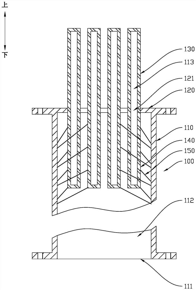
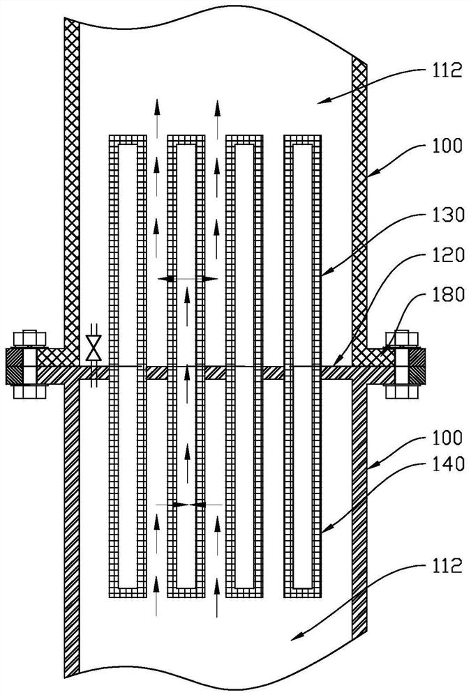
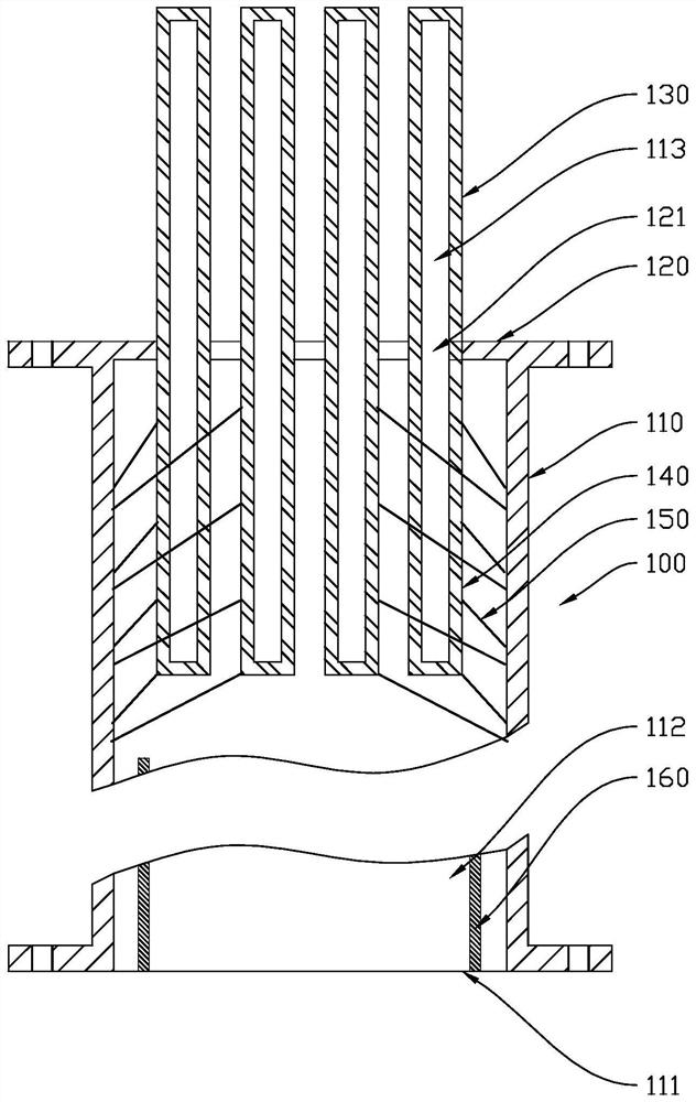
The invention discloses a heat pipe and a geothermal energy collecting device. The heat pipe comprises a sealing piece, a first pipe body, first heat transfer pieces and second heat transfer pieces. The sealing piece is provided with channels. One end of the first pipe body is provided with an opening, and the other end of the first pipe body is sealed through the sealing piece. The inner portionof the first pipe body is provided with a first cavity used for containing a heat transfer working medium. The first heat transfer pieces are connected with the sealing piece and located on one side of the sealing piece, and the inner portions of the first heat transfer pieces are provided with cavities. The second heat transfer pieces are connected with the sealing piece and located on the otherside of the sealing piece, and the inner portions of the second heat transfer pieces are provided with cavities, the cavities can communicate with the cavities in the first heat transfer pieces through the channels, so that the second heat transfer pieces and the first heat transfer pieces jointly define a second cavity used for containing the heat transfer working medium. The second cavity is isolated from the first cavity. According to the heat pipe and the geothermal energy collecting device, heat transfer can be conducted between the adjacent heat pipes through interstage heat pipes formedby the first heat transfer pieces and the second heat transfer pieces, the heat resistance of the interstage heat pipes is low, the interstage heat pipes can extend into the first cavity to be in full contact with steam, and then the heat exchange efficiency is improved beneficially.

Description

technical field [0001] The invention relates to the field of geothermal collection, in particular to a heat pipe and a geothermal collection device. Background technique [0002] As a green, low-carbon, recyclable and clean energy, geothermal resources play an increasingly prominent role in pollution control and haze reduction, changing the energy consumption structure, and improving ecological civilization. The heat pipe is a kind of heat transfer element, which can use the phase change heat transfer of the working fluid in the tube to quickly transfer the heat from the heat source to the remote end. In the related art, the heat pipe unit is usually spliced ​​by multiple heat pipes, and the adjacent heat pipes are connected by sealed plugs. However, in this way, the heat transfer resistance at the joint of the heat pipes is high, and it is difficult to transfer heat effectively. The length of the heat pipes is relatively long. The problem of heat transfer failure is prone ...

Claims


Application Information

Patent Timeline
Patent Type & Authority Applications(China)
IPC IPC(8): F28D15/02F24T10/17
CPCF28D15/0266F24T10/17Y02E10/10F28D15/0275F24T10/40F28D15/04
Inventor 朱永刚杨辉著黎永耀刘波
Owner SHENZHEN FLUENTROP TECH CO LTD
Features
  • R&D
  • Intellectual Property
  • Life Sciences
  • Materials
  • Tech Scout
  • Unparalleled Data Quality
  • Higher Quality Content
  • 60% Fewer Hallucinations
Learn More