Blasting construction technology for water diversion tunnel rock plug with high water permeability

A construction process and technology for diversion tunnels, applied in blasting and other directions, can solve the problems of threatening personnel safety, prone to leakage, affecting the effect of water intake in diversion tunnels, etc., and achieve the effect of ensuring personnel safety.

Inactive Publication Date: 2020-11-20
SINOHYDRO BUREAU 9
View PDF7 Cites 0 Cited by
  • Summary
  • Abstract
  • Description
  • Claims
  • Application Information

AI Technical Summary

Problems solved by technology

[0002] The water diversion tunnel is a kind of water conservancy facility built for taking the water accumulated in the reservoir. In the prior art, during the construction of the water diversion tunnel, rock plugs are often reserved at the end section of the water diversion tunnel, and then the rock plugs are made by blasting construction. The plug is destroyed, so that the diversion tunnel and the reservoir are connected to guide the water flow out, so as to take the water source. In the prior art, when the rock plug is destroyed by blasting, the corresponding earthwork will be washed out by the water flow. If there are more earthwork in the rock plug, then The water diversion tunnel will be blocked, resulting in a decrease in the water flow out of the water diversion tunnel, which will affect the water intake effect of the water diversion tunnel
In addition, water diversion tunnels are generally formed by excavating ground soil. Most of the underground soil adjacent to the reservoir is soaked by the water in the reservoir, and the corresponding surrounding rock becomes soft and prone to leakage, threatening to blast the rock plug. personnel safety

Method used


Image

  • Blasting construction technology for water diversion tunnel rock plug with high water permeability

Examples


Embodiment Construction

[0024] The technical solution of the present invention is further described below, but the scope of protection is not limited to the description.

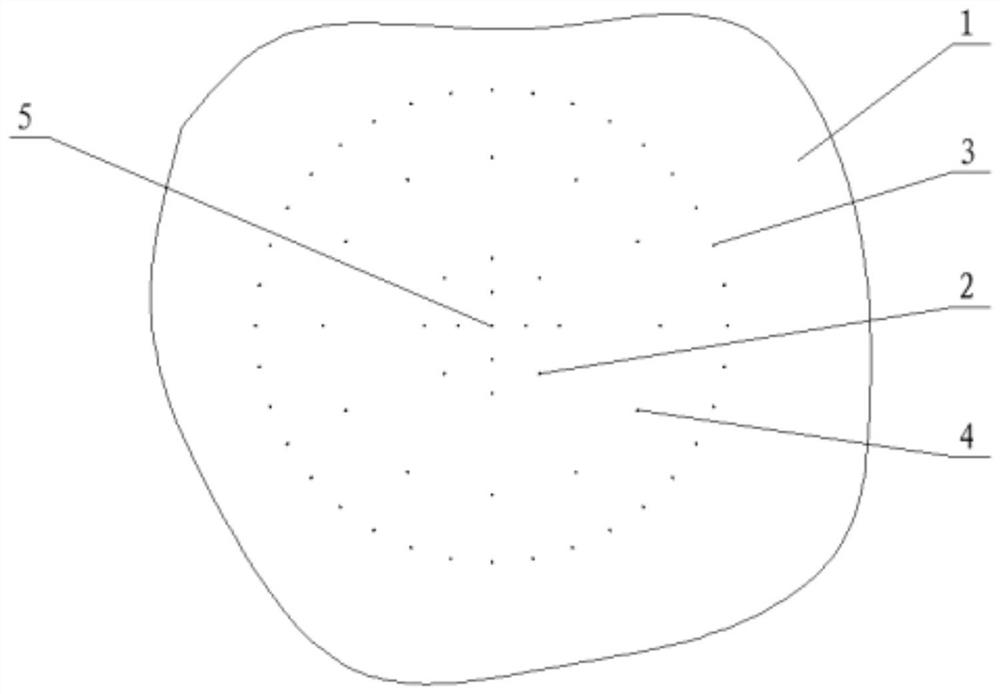
[0025] like figure 1 As shown, the present invention provides a construction technique for blasting a water diversion tunnel strong seepage rock plug, comprising the following steps:

[0026] Step 1: Excavate underground earth and stones in the area adjacent to the reservoir to form a water diversion tunnel. The earth and rocks between the end section of the water diversion tunnel and the inner wall of the reservoir form a rock plug. , investigate and obtain the volume of the rock plug as V, and then excavate earth and rocks in the water diversion tunnel to form a slag collection pit. The volume of the slag collection pit is not less than 3.2 times the volume of the rock plug;

[0027] Step 2: Use a drilling machine to drill several cut holes 2, several auxiliary holes 4 and several pre-splitting holes 3 on the blasting surface 1 ...


PUM

PropertyMeasurementUnit
Densityaaaaaaaaaa
Rateaaaaaaaaaa
Fiercenessaaaaaaaaaa

Abstract

The invention provides a blasting construction technology for a water diversion tunnel rock plug with high water permeability. The blasting construction technology comprises the following steps: excavating a water diversion tunnel, reserving the rock plug between the water diversion tunnel and a reservoir, and excavating a slag collecting pit in the water diversion tunnel; drilling cutting holes,auxiliary holes and presplitting holes in the rock plug, filling the cutting holes, the auxiliary holes and the presplitting holes with explosives and electronic detonators respectively, and hen connecting all the electronic detonators with a controller arranged outside the water diversion tunnel by detonating cords; controlling the corresponding explosives in the presplitting holes, the cutting holes and the auxiliary holes by a controller to blast and destroy the rock plug in sequence, so as to connect the water diversion tunnel with the reservoir. According to the technical scheme, the slagcollecting pit is arranged in the water diversion tunnel in advance, so that earth-rock after blasting of the rock plug is washed into the slag collecting pit by water flow, and blockage to the waterdiversion tunnel is prevented; and the presplitting holes, the cutting holes and the auxiliary holes are blasted in sequence, and surrounding rock of the rock plug is reinforced before blasting, so that water seepage in the adjacent area of the rock plug is prevented and safety of construction personnel is ensured.

Description

technical field [0001] The invention relates to the technical field of water conservancy engineering, in particular to a blasting construction technique for water diversion tunnels with strong seepage rock plugs. Background technique [0002] The water diversion tunnel is a kind of water conservancy facility built for taking the water accumulated in the reservoir. In the prior art, during the construction of the water diversion tunnel, rock plugs are often reserved at the end section of the water diversion tunnel, and then the rock plugs are made by blasting construction. The plug is destroyed, so that the diversion tunnel and the reservoir are connected to guide the water flow out, so as to take the water source. In the prior art, when the rock plug is destroyed by blasting, the corresponding earthwork will be washed out by the water flow. If there are more earthwork in the rock plug, then The water diversion tunnel will be blocked, resulting in a reduction in the water flo...

Claims


Application Information

Patent Timeline
IPC IPC(8): F42D3/04F42D1/00
CPCF42D3/04F42D1/00
Inventor 李文超任瑢瑢徐隆伟
Owner SINOHYDRO BUREAU 9
Why Eureka
Try Eureka