An automatic deviation correction device for tilt photogrammetry yaw angle of UAV

A technology of oblique photogrammetry and automatic deviation correction device, which is applied to camera devices, aircraft parts, transportation and packaging, etc. It can solve the problems of inability to achieve multi-directional focusing, inability to achieve the effect of oblique photography technology, and inability to truly reflect the situation of ground objects.

Active Publication Date: 2021-06-04
HENAN UNIVERSITY
View PDF6 Cites 0 Cited by
  • Summary
  • Abstract
  • Description
  • Claims
  • Application Information

AI Technical Summary

Problems solved by technology

[0005] The purpose of the present invention is to overcome the multi-angle oblique photography of the UAV. After the camera is rotated, the oblique camera photography points do not overlap, so it is impossible to focus from multiple directions, to truly reflect the situation of ground objects, and to achieve oblique photography. Technical effects, and the problem of not being able to detect the yaw angle in real time, design an automatic correction device for the yaw angle of the UAV tilt photogrammetry that can effectively solve the above technical problems

Method used


Image

  • An automatic deviation correction device for tilt photogrammetry yaw angle of UAV
  • An automatic deviation correction device for tilt photogrammetry yaw angle of UAV
  • An automatic deviation correction device for tilt photogrammetry yaw angle of UAV

Examples


Embodiment 1

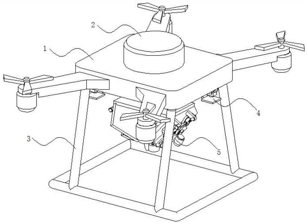
[0031] This embodiment 1 introduces an automatic deviation correction device for UAV tilt photogrammetry yaw angle, refer to the attached figure 1 And attached figure 2 , its main structure includes a UAV body 1, wherein the UAV body 1 includes a body 101, and the body 101 is provided with four wing plates 102 arranged symmetrically in the center, and the outer end lower surface of each wing plate 102 is A flight motor 103 is provided, and a propeller 104 is provided at the upper end where the output shaft of the flight motor 103 passes through the wing plate 102 . The upper surface of the drone body 1 is provided with a control module 2, and its control module 2 includes a microprocessor, a memory, a GPS locator and a built-in battery (its microprocessor, memory, and GPS locator are all shown).

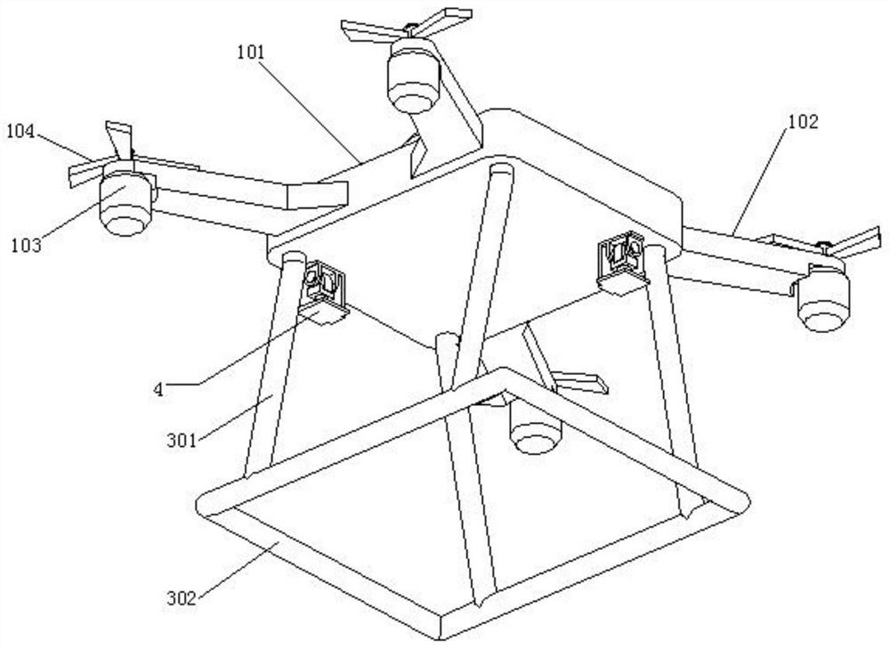
[0032] Reference attached figure 1 And attached image 3 , and the lower surface of the drone body 1 is also fixed with a lifting bracket 3, specifically its lifting legs 3 inclu...

Embodiment 2

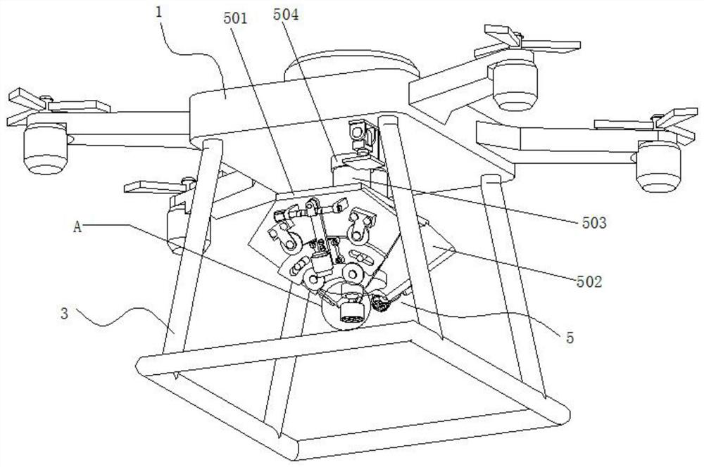
[0037] Embodiment 2 is a further improvement made on the basis of Embodiment 1, below in conjunction with the attached Figure 1~6 Explain it further.

[0038] Embodiment 2 discloses an improved UAV tilt photogrammetry yaw angle automatic correction device based on Embodiment 1. Refer to the attached figure 1 And attached figure 2 , its main structure includes a UAV body 1, wherein the UAV body 1 includes a body 101, and the body 101 is provided with four wing plates 102 arranged symmetrically in the center, and the outer end lower surface of each wing plate 102 is A flight motor 103 is provided, and the upper end of the output shaft of the flight motor 103 passing through the wing plate 102 is provided with a propeller 104 . The upper surface of the drone body 1 is provided with a control module 2, and its control module 2 includes a microprocessor, a memory, a GPS locator and a built-in battery (its microprocessor, memory, and GPS locator are all shown).

[0039] At the ...


PUM


Abstract

The invention relates to the technical field of unmanned aerial vehicle tilt photography detection, and specifically discloses an automatic deviation correction device for unmanned aerial vehicle tilt photography measurement yaw angle; it includes a drone body, and a control module is arranged on the upper surface of the drone body. The lower surface of the UAV body is fixed with a lifting bracket, and the lower surface of the UAV body is provided with a laser angle detection device in the vertical and horizontal directions, and the laser angle detection device is electrically connected to the control module. The center of the lower surface of the UAV body is provided with a yaw angle correction mechanism; the UAV of the present invention can adjust the yaw angle in real time when it is tilted to take pictures, and can truly reflect the ground objects during the adjustment process. It achieves the technical effect of oblique photography, and effectively solves the problem of difficult post-image stitching when the yaw angle is greater than 15°. It has a novel structure, excellent effect, and strong practicability.

Description

technical field [0001] The invention relates to the technical field of unmanned aerial vehicle oblique photography detection, and specifically discloses an automatic deviation correction device for unmanned aerial vehicle oblique photography measurement yaw angle. Background technique [0002] Oblique photography technology is a high-tech developed in the field of international surveying and mapping in recent years. It overturns the previous limitation that orthophoto images can only be taken from a vertical angle. By carrying multiple high-definition cameras on the same flight platform, its high-definition Set it to five, so that images can be collected from five different angles such as one vertical and four oblique at the same time, which introduces users to a real and intuitive world that conforms to human vision. Object texture information can also generate a real 3D city model through advanced positioning, fusion, modeling and other technologies. [0003] UAVs usually...

Claims


Application Information

Patent Timeline
Patent Type & Authority Patents(China)
IPC IPC(8): G05D1/08G01C11/02B64D47/08
CPCB64D47/08G01C11/02G05D1/0808
Inventor 夏浩铭陈优括赵威秦耀辰
Owner HENAN UNIVERSITY
Why Eureka
Try Eureka