
Transition roller table bearing mounting plate and machining method thereof

A transition roller and mounting plate technology, which is applied in the direction of bearing cooling, bearing components, shafts and bearings, etc., can solve the problems of inaccurate positioning, difficult splicing of transition roller table bearing mounting plates, large welding deformation, etc., to achieve convenient processing and solve Difficult splicing and precise positioning

Pending Publication Date: 2022-01-11
BENGBU TRIUMPH ENG TECH CO LTD
View PDF1 Cites 0 Cited by
  • Summary
  • Abstract
  • Description
  • Claims
  • Application Information

AI Technical Summary

Problems solved by technology

[0004] The technical problem to be solved by the present invention is to solve the problems of difficult splicing of transition roller table bearing mounting plates, inaccurate positioning, and large welding deformation

Method used

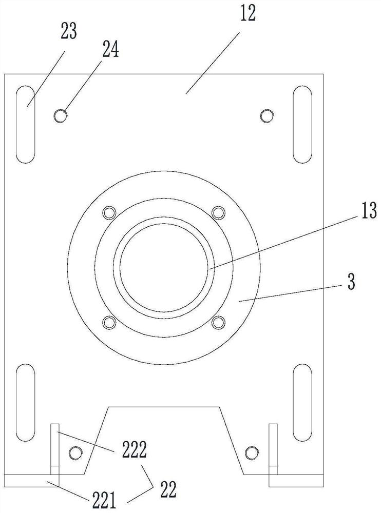
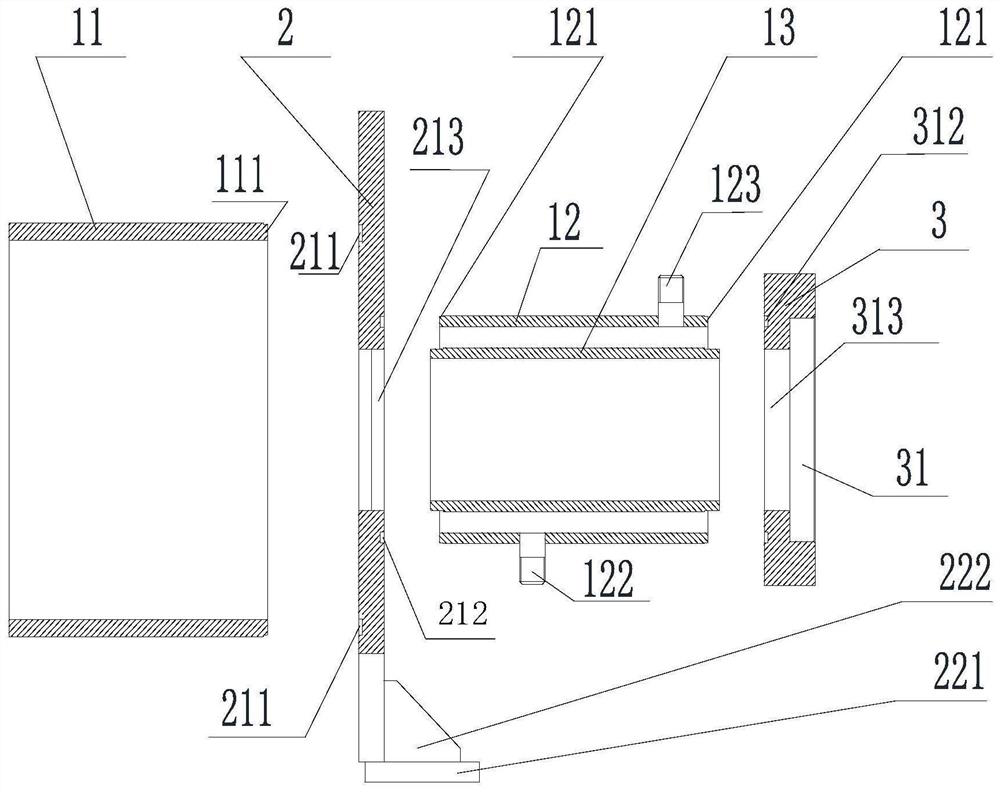
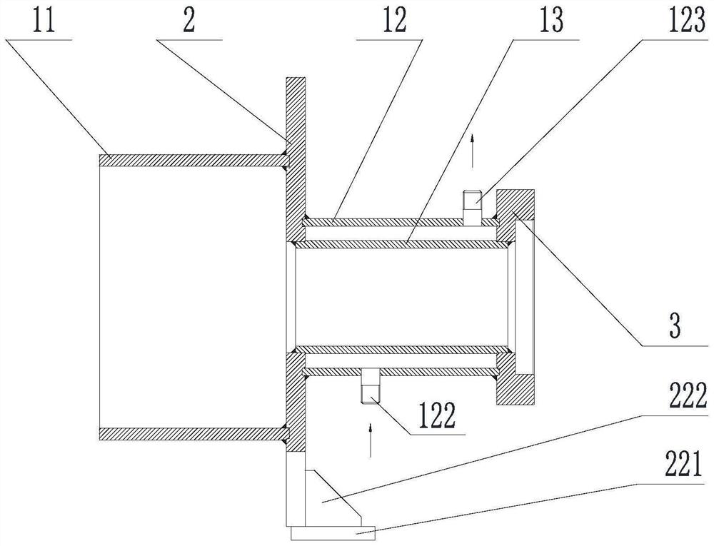

Image

  • Transition roller table bearing mounting plate and machining method thereof
  • Transition roller table bearing mounting plate and machining method thereof
  • Transition roller table bearing mounting plate and machining method thereof

Examples


Embodiment

[0037] Such as figure 1 , figure 2 , image 3 As shown, this embodiment discloses a transition roller table bearing installation plate, including a first steel pipe 11 , a middle connecting plate 2 , a second steel pipe 12 , a third steel pipe 13 and an end connecting plate 3 .

[0038] The first steel pipe 11, the second steel pipe 12, and the third steel pipe 13 are all round pipes, and the right side of the first steel pipe 11 is increased with a 3mm long annular first positioning piece 111, and the thickness dimension of the first positioning piece 111 is less than The thickness of the first steel pipe 11, the inner wall of the first positioning member 111 is flush with the inner wall of the first steel pipe 11, the outer wall of the first positioning member 111 and the outer wall of the first steel pipe 11 form a step shape, and the left side of the first steel pipe 11 The side is connected with the sealed box.

[0039] The two ends of the second steel pipe 12 are incre...


PUM


Abstract

The invention provides a transition roller table bearing mounting plate and a machining method thereof. The inner diameters of a second steel pipe and a third steel pipe are smaller than those of a first steel pipe, the second steel pipe is arranged on the third steel pipe in a sleeving manner and is coaxially arranged to form an internal space, and the two ends of the third steel pipe extend out of the second steel pipe; the right side of the first steel pipe is provided with a first positioning piece, and the two ends of the second steel pipe are provided with second positioning pieces; the left side face of a middle connecting plate is provided with an annular first positioning groove matched with the first positioning piece; second positioning grooves matched with the second positioning pieces are formed in the right side face of the middle connecting plate; a first through hole for accommodating the third steel pipe is formed in the middle of the middle connecting plate; and third positioning grooves matched with the second positioning pieces are formed in the left side face of an end connecting plate, and a second through hole connected with the third steel pipe is formed in the middle of the left side face of the end connecting plate. The positioning pieces are clamped with the positioning grooves in a matched mode, accurate positioning is achieved, the machining process is decomposed, and the problems that splicing is difficult and welding deformation is large are solved.

Description

technical field [0001] The invention relates to the field of glass machining, in particular to a transition roller table bearing mounting plate and a processing method thereof. Background technique [0002] Usually, in the process of producing the bearing mounting plate of the transition roller table at the hot end of the glass production line, due to the complex structure of the bearing mounting plate and the connection of multi-layer steel pipes and steel plates, it is difficult to align the centerlines of the steel pipes and steel plates when splicing by conventional methods. Difficult, the welding deformation is also large, the structure after welding is uneven, and the sealing is poor, which doubles the difficulty of later processing, and the processing and forming quality of the bearing seat is low, which does not meet the design requirements. [0003] The patent with the application number "201921846501.6" discloses a quick detachable bearing seat device for the trans...

Claims


Application Information

Patent Timeline
Patent Type & Authority Applications(China)
IPC IPC(8): F16C35/00F16C37/00B23K31/02B23K37/053
CPCF16C35/00F16C37/00B23K31/02B23K37/053
Inventor 吴渠张德三俞泽田翟毅严俊俞茂徐伟徐星
Owner BENGBU TRIUMPH ENG TECH CO LTD
Learn More