Section steel splicing device

A splicing device and section steel technology, which is applied in construction, excavation, and infrastructure engineering, can solve the problems of incorrect assembly, impact on construction period, and low processing efficiency, so as to facilitate design and construction, improve overall stability, and improve construction efficiency effect

Pending Publication Date: 2022-07-05
深圳市巨鲲科技有限公司
View PDF0 Cites 0 Cited by
  • Summary
  • Abstract
  • Description
  • Claims
  • Application Information

AI Technical Summary

Problems solved by technology

There are the following problems: 1. Too many bolt holes on the section steel not only have low processing efficiency and high cost, but also weaken the strength and bearing capacity of the section steel; 2. When there are too many assembled section steels, due to hole position processing errors, the assembly is often not correct , Difficult to assemble, which affects the construction period; 3. The position of the connector is limited and cannot be adjusted. When there is a bracket underneath or conflicts with other components, it cannot be avoided, which affects design and construction

Method used


Image

  • Section steel splicing device
  • Section steel splicing device
  • Section steel splicing device

Examples


Embodiment Construction

[0030] The present invention will be further described below with reference to the accompanying drawings and specific embodiments.

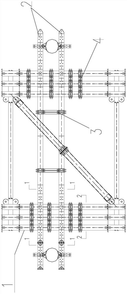
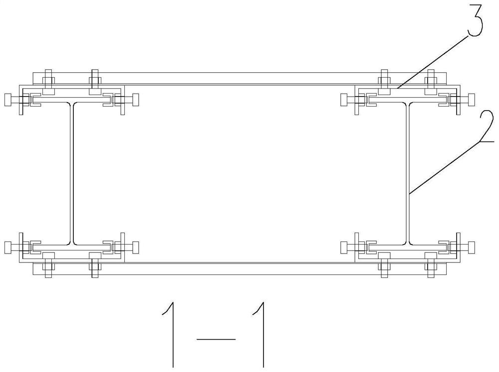
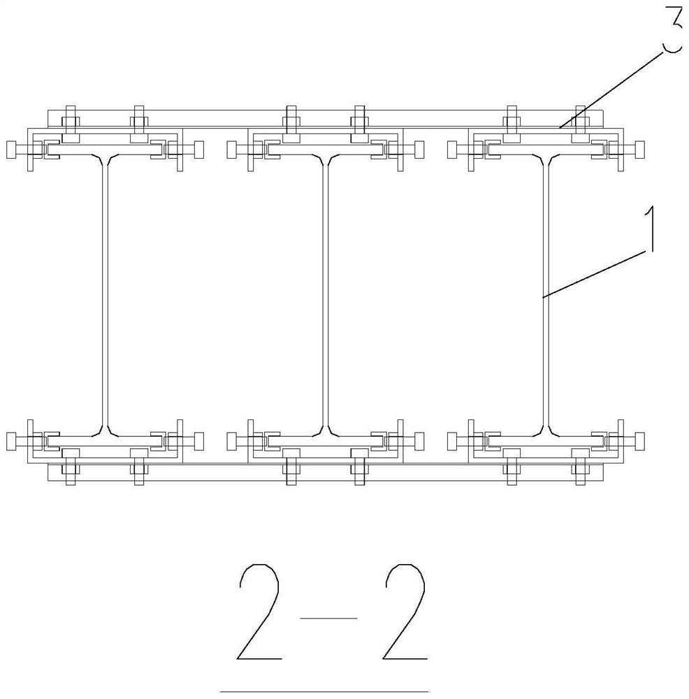
[0031] see Figure 1-Figure 8 , a profiled steel splicing device, comprising a connecting piece 301 and a high-strength fixture 302; the high-strength fixture 302 comprises a channel-shaped piece 302a, the channel-shaped piece 302a includes a channel-shaped steel 302a2 and a nut 302a1, and the channel-shaped steel 302a2 has a The connecting piece 301 is attached to a fastened plane, and two sides of the plane extend vertically in the same direction with a bent portion. At least a pair of nuts 302a1 are screwed and installed on the bent portion and face each other. The front end of the nut 302a1 is fixedly connected with the U-shaped buckle 302c, and a pair of the U-shaped buckles 302c forms a tendency to snap and clamp the edge portion of the shaped steel part.

[0032] In this example, see figure 1 , the profiled steel component is the profile...


PUM


Abstract

The invention relates to a profile steel splicing device which comprises a connecting piece and a high-strength clamp. The high-strength clamp comprises a groove-shaped piece, the groove-shaped piece comprises groove-shaped steel and nuts, the groove-shaped steel is provided with a plane attached and fastened to the connecting piece, the two sides of the plane vertically extend in the same direction to form bent parts respectively, at least one pair of nuts are installed on the bent parts in a screwed connection mode and are opposite, and the front ends of the nuts are fixedly connected with U-shaped buckles. And the pair of U-shaped buckles tends to clamp and clamp the edge wing part of the profile steel part. Bolt holes do not need to be formed in the profile steel, a troublesome procedure is omitted, the machining efficiency is improved, and the machining cost is reduced; bolt holes are not formed, so that weakening of the bearing capacity of the profile steel by the bolt holes is avoided; construction is convenient, the degree of freedom is high, the construction efficiency is improved, and splicing difficulty caused by hole site machining errors can be avoided; the device can be freely adjusted when colliding with the support, and design and construction are convenient; the support beams are connected through the device, the overall stability is improved, and then the safety of the whole system is guaranteed.

Description

technical field [0001] The invention relates to a profile steel splicing device, which belongs to the technical field of building construction. Background technique [0002] In order to ensure the safety of the construction of the underground structure and the surrounding environment of the foundation pit, it is necessary to adopt the support, reinforcement and protection measures for the side wall of the foundation pit and the surrounding environment. Whether it is a high-rise building or a deep foundation pit project for subway construction, since most of the excavation is carried out in the city, there are usually various structures such as traffic arteries, existing buildings or pipelines around the foundation pit. Safety, and saving construction period and cost, steel support system is widely used. [0003] In the prior art, the steel supports of the foundation pit are often spliced ​​side-by-side with several sections of steel to meet the requirements of assembly and ...

Claims


Application Information

Patent Timeline
Patent Type & Authority Applications(China)
IPC IPC(8): E02D17/04
CPCE02D17/04
Inventor 刘建鹏王震唐涛
Owner 深圳市巨鲲科技有限公司
Why Eureka
Try Eureka