A micro-energy grid system and its collaborative optimization operation control method

A technology of operation control and collaborative optimization, applied in the directions of solar heating system, design optimization/simulation, single network parallel feeding arrangement, etc. Restricting the local consumption of renewable energy and other issues, to achieve the effect of improving comprehensive utilization efficiency, alleviating environmental pollution pressure, and reducing loss

Active Publication Date: 2022-06-17
INNER MONGOLIA UNIV OF SCI & TECH
View PDF10 Cites 1 Cited by
  • Summary
  • Abstract
  • Description
  • Claims
  • Application Information

AI Technical Summary

Problems solved by technology

[0003] At present, the operation of the micro-energy grid is mainly based on the Combined Cooling Heating and Power (CCHP) system, which assists wind, light and other renewable energy power generation, and in terms of load, it is only divided into cooling load, heating load and The electric load does not refine the energy demand of users, and at the same time, it does not consider the step-by-step utilization of energy and the comprehensive utilization of renewable energy on the energy supply side and energy consumption side, resulting in insufficient comprehensive energy utilization efficiency and restricting renewable energy. Full local consumption of energy

Method used


Image

  • A micro-energy grid system and its collaborative optimization operation control method
  • A micro-energy grid system and its collaborative optimization operation control method
  • A micro-energy grid system and its collaborative optimization operation control method

Examples


Embodiment 1

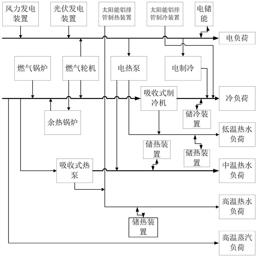
[0032] This embodiment is used to provide a micro-energy grid system, the system is a micro-energy grid system composed of power supply, heating and cooling that operates independently of multiple energy flows, and constitutes a micro-energy grid through source-grid-load-storage network. like figure 1 As shown, the micro-energy grid system includes an energy supply side, an energy conversion device and a load side; the energy supply side includes a wind power generation device, a photovoltaic power generation device, a solar aluminum exhaust pipe heating device, a solar aluminum exhaust pipe refrigeration device and a gas a boiler; the load side includes an electric load, a cooling load and a heat load; the heat load includes a low temperature hot water load, a medium temperature hot water load, a high temperature hot water load and a high temperature steam load; the energy conversion device includes an electric heat pump; In a micro-energy grid system provided by this embodi...

Embodiment 2

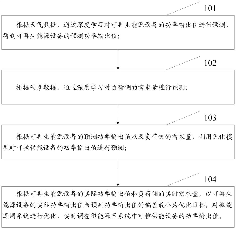
[0063] This embodiment is used to provide a collaborative optimal operation control method for a micro-energy grid system, which controls the above-mentioned micro-energy grid system to work, taking into account the randomness and volatility of the power output of renewable energy equipment within a short time scale of the micro-energy grid system The real-time rolling optimization operation of micro-energy grid equipment is realized by the method of model predictive control. like figure 2 As shown, the collaborative optimization operation control method includes the following steps:

[0064] Step 101, according to the weather data, predict the power output value of the renewable energy equipment through deep learning, and obtain the predicted power output value of the renewable energy equipment; the weather data includes air temperature, humidity, air pressure, air density, solar radiation intensity , cloud coverage, surface temperature, wind speed and wind direction; the r...


PUM


Abstract

The invention relates to a micro-energy network system and its collaborative optimization operation control method. By rationally configuring the energy supply side and the specific equipment contained in the energy conversion device, the micro-energy network system formed not only has a higher proportion of new energy access , through the optimized configuration of the energy storage device, the user's energy demand can be met through the power grid, heating network and gas network, and the basic balance between local energy production and user energy load can be achieved. Rolling optimization continuously adjusts the power output value of the controllable energy supply equipment in the micro-energy grid system, and makes the micro-energy grid system operate economically under the premise of meeting the real-time balance of supply and demand, so as to achieve the purpose of energy saving. Unified and coordinated scheduling of energy consumption, energy supply and energy storage, realize the complementarity of multiple energy supplies in the micro-energy network system, improve the comprehensive utilization efficiency and step utilization of multiple energy supplies in the micro-energy network, reduce emissions, and realize energy consumption on the spot.

Description

technical field [0001] The invention relates to the field of comprehensive energy utilization, in particular to a micro-energy grid system and a coordinated optimal operation control method thereof. Background technique [0002] Energy is an important guarantee for human survival and the lifeblood of economic and social development. With the development of society and the improvement of people's living standards, human's demand for energy is increasing year by year, resulting in increasingly depleted primary fossil energy and increasingly serious environmental problems. To improve energy efficiency and reduce CO 2 Emissions, the realization of sustainable social development, and the combination of traditional energy systems and renewable energy power generation such as solar energy and wind energy have attracted more and more attention. and live. However, the microgrid is only limited to electric energy, and lacks the coupling and coordinated operation with various energy...

Claims


Application Information

Patent Timeline
Patent Type & Authority Patents(China)
IPC IPC(8): H02J3/00H02J3/46F22B1/22F24S20/20F25B30/06G06F30/27G16Y10/35G16Y20/30G16Y40/30G06F111/04
CPCH02J3/00H02J3/003H02J3/466F22B1/22F24S20/20F25B30/06G06F30/27G16Y10/35G16Y20/30G16Y40/30H02J2300/22H02J2300/28G06F2111/04Y02E10/40
Inventor 杨培宏刘景霞亢岚魏毅立张继红吴振奎张自雷
Owner INNER MONGOLIA UNIV OF SCI & TECH
Why Eureka
Try Eureka