Muffle reduction ironmaking device

A flame trap and flame trap technology, applied in the non-blast furnace ironmaking field, can solve the problems of low metallization rate, low flue gas utilization efficiency, high energy consumption, etc., achieve high metallization rate, realize efficient reduction, and improve metallization rate effect

Pending Publication Date: 2020-12-11
钢研晟华科技股份有限公司 +1
View PDF9 Cites 0 Cited by
  • Summary
  • Abstract
  • Description
  • Claims
  • Application Information

AI Technical Summary

Problems solved by technology

[0004] In view of the above analysis, the present invention aims to provide a flame reduction ironmaking device, which solves the pr

Method used


Image

  • Muffle reduction ironmaking device
  • Muffle reduction ironmaking device
  • Muffle reduction ironmaking device

Examples


Embodiment 1

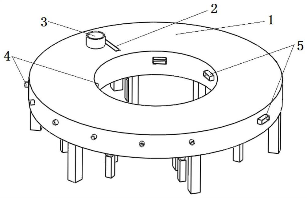
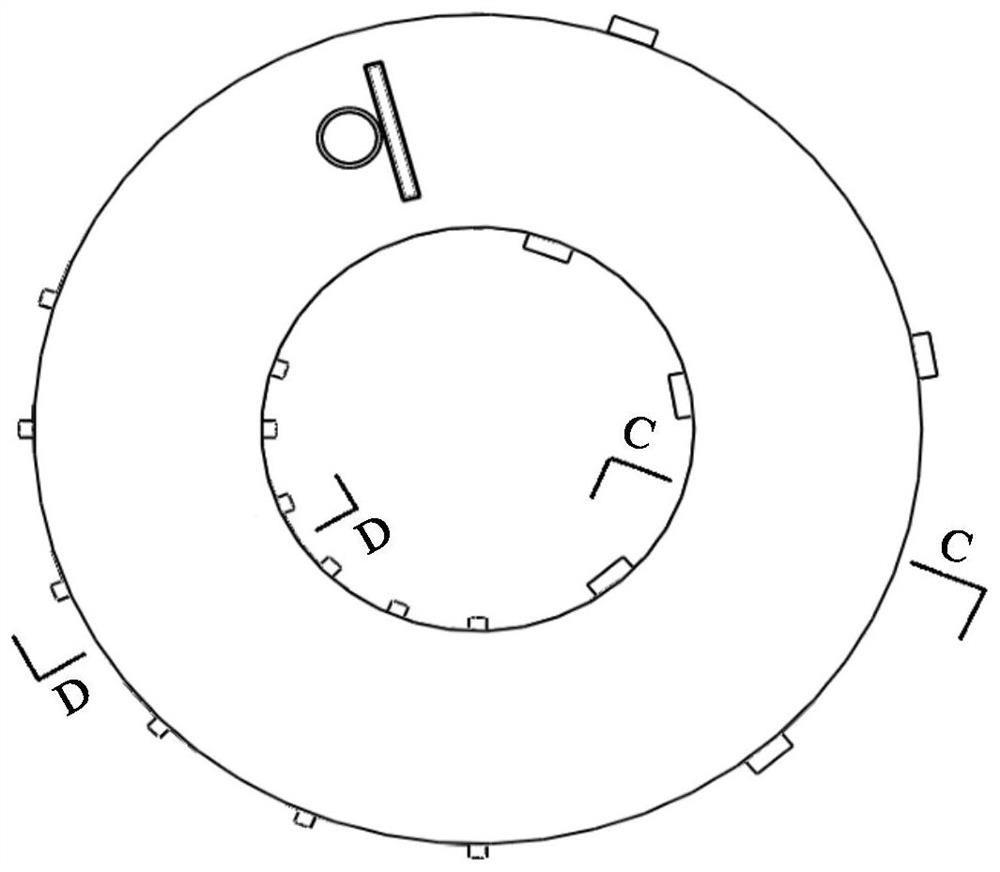
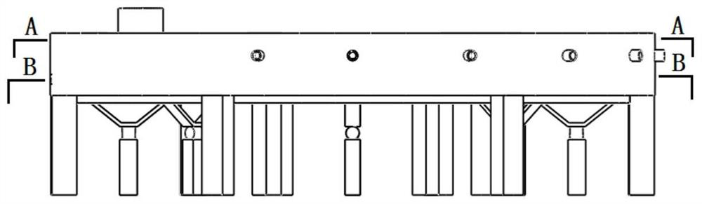
[0051] The invention provides a flame reduction ironmaking device, see Figure 1 to Figure 8, comprising a rotary hearth furnace 1, the inner space of the rotary hearth furnace 1 is divided into a heating section and a reducing section along the axial direction of the rotary hearth furnace 1 through a partition wall 6 arranged radially, the heating section is a heating chamber 14, and the reducing section is The axial direction of the bottom furnace 1 is divided into a reduction chamber 12 and a combustion chamber 10 located above the reduction chamber 12 through a flame shield 11. The combustion chamber 10 is set independently and does not communicate with the heating chamber 14 and the reduction chamber 12. The heating chamber 14 has a feeding port 2. The reduction chamber 12 is provided with a discharge port 8, and the combustion gas is passed into the heating chamber 14 and the combustion chamber 10.

[0052] During implementation, the furnace bottom 13 of the rotary heart...

Embodiment 2

[0073] This embodiment provides a method for direct reduction ironmaking in a muffled rotary hearth furnace, using the muffled reduction ironmaking device provided in Example 1, see Figure 9 , including the following steps:

[0074] Step 1: Iron-containing raw materials, flux and coal powder are mixed according to the design ratio, and the carbon-containing pellets after briquetting or pelletizing are directly loaded into the heating chamber 14 of the rotary hearth furnace 1, and the combustion gas in the heating chamber 14 (such as , air and / or oxygen) to carry out open flame preheating of carbonaceous pellets;

[0075]Step 2: The preheated carbon-containing pellets enter the reduction chamber 12 with the rotation of the bottom of the rotary hearth furnace 1, and the combustion gas in the combustion chamber 10 above the reduction chamber 12 is burned, and the preheated pellets are passed through the flame shield 11. The carbon-containing pellets are heated through the flame...


PUM


Abstract

The invention discloses a muffle reduction ironmaking device, belongs to the technical field of non-blast furnace ironmaking, and solves the problems of low metalization ratio, low flue gas utilization efficiency and high energy consumption of an existing rotary hearth furnace. The muffle reduction ironmaking device comprises a rotary hearth furnace. The inner space of the rotary hearth furnace isdivided into a heating segment and a reduction segment through a partition wall in the axial direction of the rotary hearth furnace, and the partition wall is arranged in the radial direction. The heating segment is a heating chamber, and the reduction segment is divided into a reduction chamber and a combustion chamber located above the reduction chamber through a muffle plate in the axial direction of the rotary hearth furnace. A feed port is formed in the heating chamber, a discharge port is formed in the reduction chamber, and combustion gas is introduced into the heating chamber and thecombustion chamber. The ironmaking device can be used for reduction of iron-containing furnace charge.

Description

technical field [0001] The invention belongs to the technical field of non-blast furnace ironmaking, and in particular relates to a flame reduction ironmaking device. Background technique [0002] Blast furnace ironmaking is the most important ironmaking process in the world today. It has the characteristics of large production scale, low energy consumption, good quality pig iron, and high efficiency. However, there are two main problems in blast furnace ironmaking: first, blast furnace ironmaking needs to consume a large amount of fuel, especially high-quality coke, and the shortage of coking coal resources and high coke prices restrict the blast furnace ironmaking production; second, blast furnace ironmaking CO 2 Large emissions and serious environmental pollution lead to global warming. [0003] The technical feature of non-blast furnace ironmaking is to get rid of the dependence of blast furnace ironmaking on coking coal resources and use non-coking coal to make iron. ...

Claims


Application Information

Patent Timeline
IPC IPC(8): C21B13/08
CPCC21B13/08C21B13/0073
Inventor 高建军万新宇王锋严定鎏齐渊洪林万舟
Owner 钢研晟华科技股份有限公司
Why Eureka
Try Eureka