Strong coupling magnetic coupling for micro turbojet engine

A turbojet engine and magnetic coupling technology, which is applied in the direction of machines/engines, electric brakes/clutches, permanent magnet clutches/brakes, etc., can solve the problem of very high machining accuracy and installation accuracy, and uneven force on contact points , uncontrollable vibration and other problems, to achieve the effect of solving large vibration, reducing vibration, and uniform transmission force

Pending Publication Date: 2020-11-20
西安觉天动力科技有限责任公司
View PDF0 Cites 0 Cited by
  • Summary
  • Abstract
  • Description
  • Claims
  • Application Information

AI Technical Summary

Problems solved by technology

Due to the uneven force on the contact point, the vibration is uncontrollable when the coupling is in contact with the engine rotor. Taking a certain type of 40kgf turbojet engine as an example, the vibration becomes larger as the wear increases, and the measured vibration acceleration value increases from 5g to 15g; Moreover, the existing couplings have very high requirements on machining accuracy and installation accuracy, which is not conducive to mass production

Method used


Image

  • Strong coupling magnetic coupling for micro turbojet engine
  • Strong coupling magnetic coupling for micro turbojet engine

Examples


Embodiment 1

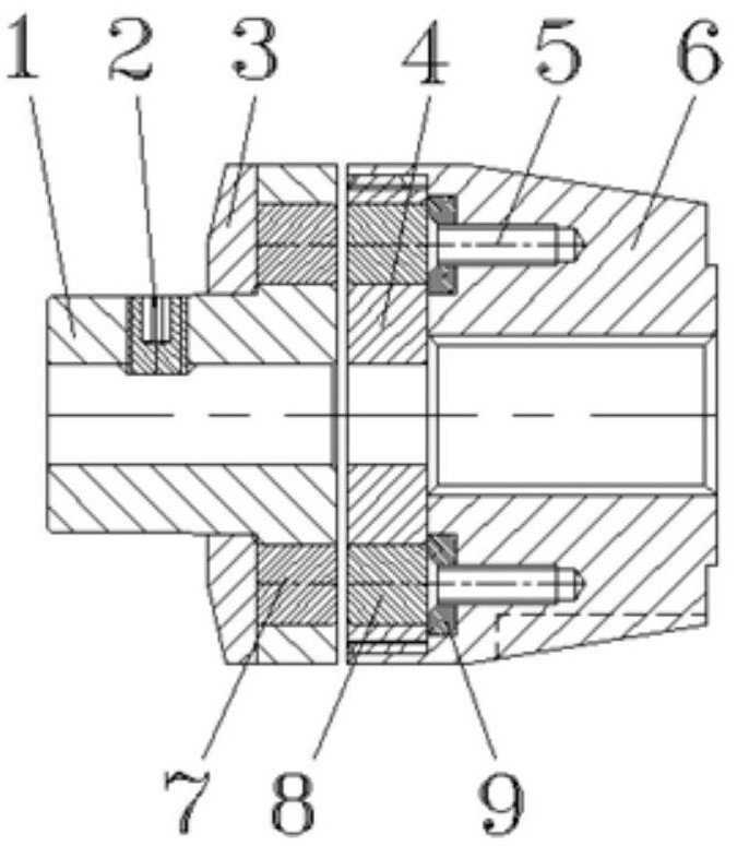
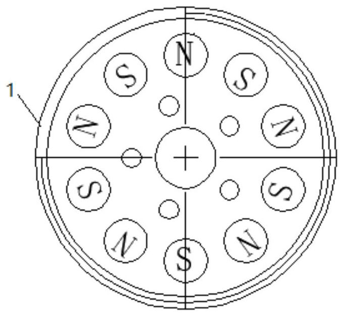
[0017] Example 1, such as figure 1 , figure 2 As shown, a strong coupling magnetic coupling for a miniature turbojet engine, including the coaxial arrangement of the drive shaft of the turbine engine and the rotating shaft of the generator, the connecting end of the rotating shaft of the generator is equipped with a motor coupling Shaft 1, the connecting end of the drive shaft of the turbine engine is equipped with a rotor nut 6, and the rotor nut 6 is connected with a rotor coupling flange 4; the motor coupling 1 and the rotor coupling flange At least two first neodymium boron magnets 7 with alternating magnetic poles are installed on the connecting end surface of 4, and the connecting surface of the rotor coupling flange 4 and the motor coupling 1 is equipped with alternating magnetic poles corresponding to the first neodymium boron magnets 7. The second neodymium boron magnet 8 . The connecting end face of the motor coupling 1 is set corresponding to the connecting end f...

Embodiment 2

[0021] Embodiment 2: Same as Embodiment 1, the difference is that after installation, the centerline of the motor coupling 1 is aligned with the centerline of the rotor nut 6, and the distance between the two intermediate connections is 0.3mm. The first neodymium-boron magnets 7 and the second neodymium-boron magnets 8 are correspondingly installed in eight evenly distributed in the circumferential direction.

Embodiment 3

[0022] Embodiment 3: Same as Embodiment 1, the difference is that after installation, the centerline of the motor coupling 1 is aligned with the centerline of the rotor nut 6, and the distance between the two intermediate connections is 0.5mm. There are 10 first neodymium boron magnets 7 and second neodymium boron magnets 8 that are evenly distributed in the circumferential direction.


PUM


Abstract

The invention belongs to the technical field of micro turbojet engines. The invention discloses a strong coupling magnetic coupling for a micro turbojet engine. The strong coupling magnetic coupling comprises a driving shaft of the turbine engine, wherein the driving shaft of the turbine engine and a rotating shaft of the generator are coaxially arranged, a motor coupler is installed at the connecting end of the rotating shaft of the generator, a rotor nut is installed at the connecting end of the driving shaft of the turbine engine, and a rotor coupler flange is connected to the rotor nut. Atleast two first neodymium-boron magnets with alternate magnetic poles are installed on the connecting end face of the motor coupling and the rotor coupling flange, and second neodymium-boron magnetswith alternate magnetic poles corresponding to the first neodymium-boron magnets are installed on the connecting face of the rotor coupling flange and the motor coupling. Hard-contact-free two-way transmission can be achieved between the motor and the engine rotor, transmission stress is uniform, engine vibration is greatly reduced, cost is low, and the problem of large vibration in the prior artis solved.

Description

technical field [0001] The invention belongs to the technical field of micro-turbojet engines, and in particular relates to a strong coupling magnetic shaft coupling for micro-turbojet engines. Background technique [0002] The micro-turbine engine is used for small unmanned aerial vehicles, target drones or missiles. When starting, the starter motor installed at the front end of the engine drives the rotor parts to rotate to a certain speed. After the engine is injected and ignited, the engine rotor parts and the starting The motor disengages. The starter motor does not have the function of generating electricity. According to the needs of the aircraft, the starter motor can be replaced by a generator. After the start is successful, the rotor part of the micro-turbojet engine drives the generator to generate electricity, providing a certain amount of power to the aircraft and reducing battery life. load and improve engine efficiency. [0003] The existing shaft coupling c...

Claims


Application Information

Patent Timeline
IPC IPC(8): H02K49/10F02C7/268
CPCF02C7/268H02K49/102H02K49/108
Inventor 黄新春陈玉春刘鸽
Owner 西安觉天动力科技有限责任公司
Why Eureka
Try Eureka