Supercharge Your Innovation With Domain-Expert AI Agents!

Hydraulic motor vehicle braking system and method for operating same

A technology of hydraulic braking and motor vehicles, which is applied in the direction of brake control system, brake action activation device, brake, etc., and can solve the problem of the driver activating the brake pedal, etc.

Active Publication Date: 2020-11-20
LUCAS AUTOMOTIVE GMBH
View PDF5 Cites 2 Cited by
  • Summary
  • Abstract
  • Description
  • Claims
  • Application Information

AI Technical Summary

Problems solved by technology

However, it cannot be assumed that the driver is also in the vehicle in such situations (e.g. in Remote Control Park (RCP) mode), or that the driver can immediately activate the brake pedal for PT mode (e.g. if the driver's eyes away from the road ahead)

Method used


Image

  • Hydraulic motor vehicle braking system and method for operating same
  • Hydraulic motor vehicle braking system and method for operating same
  • Hydraulic motor vehicle braking system and method for operating same

Examples


Embodiment Construction

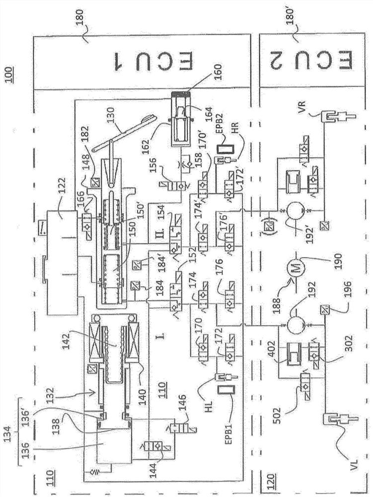
[0034] figure 1 A hydraulic circuit diagram of a first exemplary embodiment of a motor vehicle hydraulic braking system 100 using the BBW principle is shown in . Braking system 100 is designed to be suitable for autonomous or semi-autonomous driving.

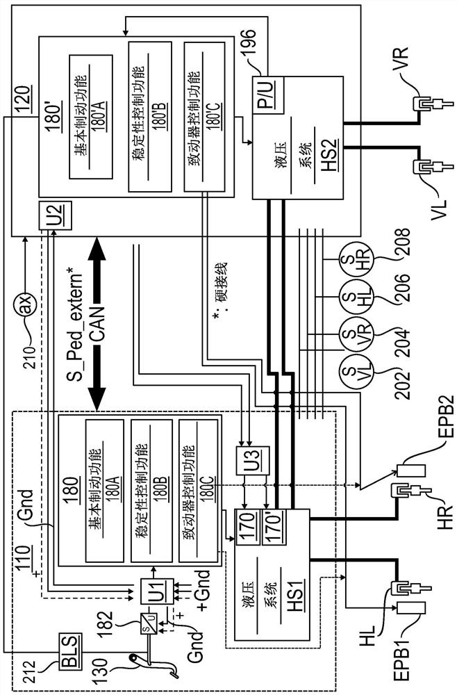
[0035] Such as figure 1 As shown, the braking system 100 comprises a first functional unit 110 which provides an electrically actuatable main braking function and a second functional unit 120 which implements the electrically actuatable main braking function in a redundant manner. auxiliary braking function. The first functional unit 110 is designed to build up brake pressure at the two front wheel brakes VL, VR and the two rear wheel brakes HL, HR of a double-axle motor vehicle, while the second functional unit 120 is designed to only Brake pressure builds up at the two wheel brakes VL, VR of the wheels. In an alternative exemplary embodiment, the second functional unit 120 can be designed only at the two wheel brakes HL, H...


PUM


Abstract

The invention relates to a hydraulic motor vehicle braking system comprising a first sensor device, a first functional unit, a second functional unit and a switching device. The first functional unitcomprises at least one first electrical brake pressure generator, by means of which a brake pressure can be generated on respective wheel brakes, and a first control system which is designed to control the at least one first electrical brake pressure generator on the basis of a sensor signal of the sensor device. The second functional unit comprises at least one second electrical brake pressure generator, by means of which a brake pressure can be respectively generated on a subset of the wheel brakes, and a second control system which is designed to control the at least one second electrical brake pressure generator on the basis of the sensor signal in the event of a failure of the first functional unit. The switching device is designed to couple the first sensor device optionally to the first control system or the second control system according to the operability of the first functional unit.

Description

technical field [0001] This document relates generally to the field of motor vehicle braking systems. In particular, a motor vehicle hydraulic braking system and method of operation are described. Background technique [0002] Conventional motor vehicle hydraulic braking systems using the brake-by-wire (BBW) principle include an electric brake pressure generator which generates brake pressure at the wheel brakes in normal braking mode. For this purpose, the deceleration of the vehicle requested by the driver at the brake pedal is detected by a sensor and converted into an activation signal for the electric brake pressure generator. [0003] In order to still be able to build up brake pressure at the wheel brakes even in the event of failure of the electric brake pressure generator, hydraulic brake systems using the BBW principle usually also include a master cylinder via which hydraulic fluid can also be delivered to the wheel brakes. In normal braking mode, the brake ped...

Claims


Application Information

Patent Timeline
Patent Type & Authority Applications(China)
IPC IPC(8): B60T13/66B60T13/74
CPCB60T13/662B60T13/745B60T8/4081B60T7/042B60T11/165B60T13/161B60T13/58B60T2220/04B60T2240/00B60T2270/402B60T2270/404B60T2270/82
Inventor N·艾尔福德A·马克思
Owner LUCAS AUTOMOTIVE GMBH
Features
  • R&D
  • Intellectual Property
  • Life Sciences
  • Materials
  • Tech Scout
  • Unparalleled Data Quality
  • Higher Quality Content
  • 60% Fewer Hallucinations
Learn More