
Switching profile

A technology of contour parts and switches, which is applied in the direction of electric switches, electrical components, wing fan parts, etc., to achieve the effect of facilitating assembly and reducing assembly time

Pending Publication Date: 2020-11-20
ベーベーツェー ビルヒャー アクチェンゲゼルシャフト
View PDF6 Cites 0 Cited by
  • Summary
  • Abstract
  • Description
  • Claims
  • Application Information

AI Technical Summary

Problems solved by technology

The contact strip can only be compressed by changing the aspect ratio of the chamber

Method used


Image

  • Switching profile
  • Switching profile
  • Switching profile

Examples


Embodiment Construction

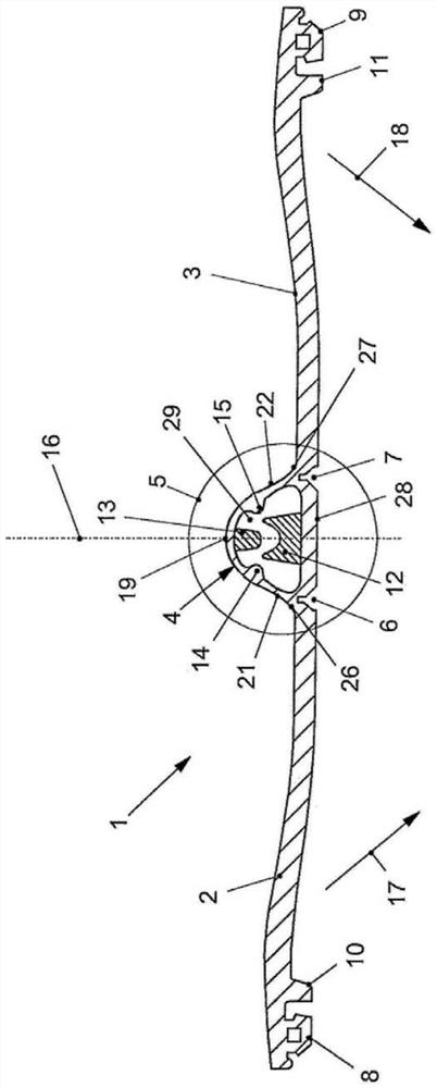
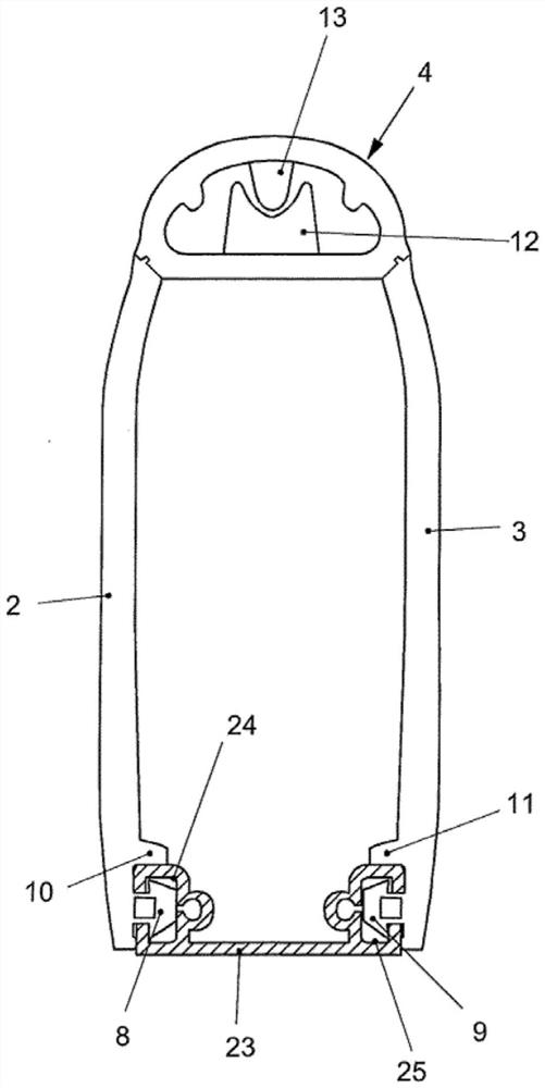
[0025] figure 1 A side sectional view of the switch profile 1 is shown. The switching profile 1 essentially comprises three elements. The switch head 4 is shown centered. A first limb 2 on one side and a second limb 3 on the other side extend separately from the switching head 4 .

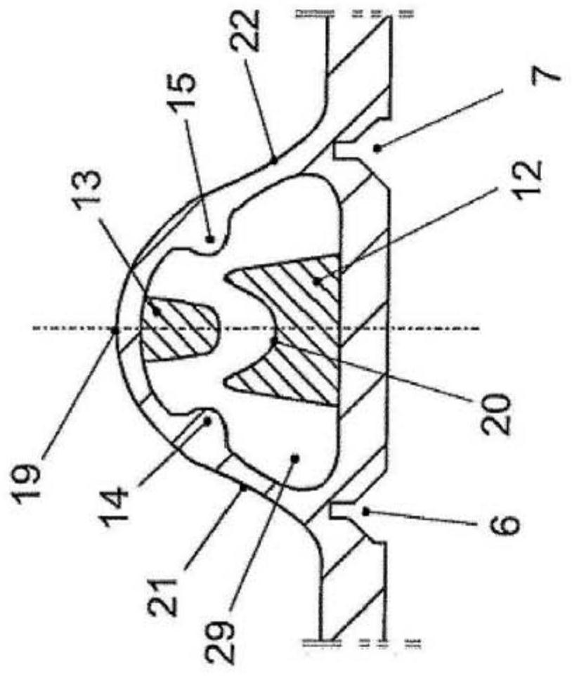
[0026] figure 1 Also shown is a section 5, which is at figure 2 is enlarged.

[0027] A first folding channel 6 is shown where the first side flap 2 is molded to the switch head 4 . The first folding channel 6 tapers towards the first joining point 26 . In the same way, a second folding channel 7 is formed at the second joining point 27 . The second folding channel 7 also tapers towards the second joining point 27 . The first folding channel 6 and the second folding channel 7 open away from the switch head 4 .

[0028] The first side flap 2 has a first folding channel 6 at one end. At the other end, the first flank 2 has a first connecting piece 8 . The first connecting piece 8 is an ex...


PUM


Abstract

The invention relates to a switching profile (1) with a switching head (4) and a first side wing (2) and a second side wing (3), wherein a convex profile (12) and a concave profile (13) are arranged in a manner oriented towards one another in an interior (29) of the switching head (4), wherein the switching head (4) consists of a base (28), a first side flank (21) and a second side flank (22), wherein the first side flank (21) projects away from the base (28) at one end and merges into a crown (19) at the other end, wherein the second side flank (22) projects away from the base (28) at one endand likewise merges into the crown (19) at the other end.

Description

technical field [0001] The invention relates to a switching profile according to the preamble of claim 1 . Background technique [0002] Such switching profiles are known and used in various forms and designs. [0003] For example, in EP1926113A1 an overrun profile is disclosed, in particular for a door or gate with drive, which reacts to a pressure signal, and whose rubber profile has a switch chamber for receiving at least one motorized switching strip and / or pressure wave contact device as switching element, and an overrunning strip which is force-transmittingly connected to the switching chamber so that the dimensions of the net cross-section of the switching chamber can be varied; thus, The switch chamber is equipped with pivoting lever arms, such as flanges, rods, protrusions or the like, by which the switch chamber can be changed in size when the lever arm is pivoted to assemble the overrunning profile, so that when the lever arm pivots to perform The switching elem...

Claims


Application Information

Patent Timeline
IPC IPC(8): E05F15/44
CPCE05F15/44E05Y2800/455H01H2003/165H01H3/161E05Y2400/445E05Y2900/132
Inventor 迪特玛尔·霍思普海因茨·马歇尔
Owner ベーベーツェー ビルヒャー アクチェンゲゼルシャフト
Learn More