Screw thread forming equipment

A technology for forming equipment and threads, applied in the field of screw thread forming equipment, can solve the problems of manual and repeated placement, and achieve the effect of reducing workload, reducing errors and consistent positions

Active Publication Date: 2020-11-24
南京力迅螺杆有限公司
View PDF11 Cites 3 Cited by
  • Summary
  • Abstract
  • Description
  • Claims
  • Application Information

AI Technical Summary

Problems solved by technology

[0005] In order to overcome the disadvantage of manually placing and taking out the screw repeatedly when threading the screw, the technical problem to be solved by the present invention is to provide a screw thread forming equipment that does not need to manually place and take out the screw

Method used


Image

  • Screw thread forming equipment
  • Screw thread forming equipment
  • Screw thread forming equipment

Examples


Embodiment 1

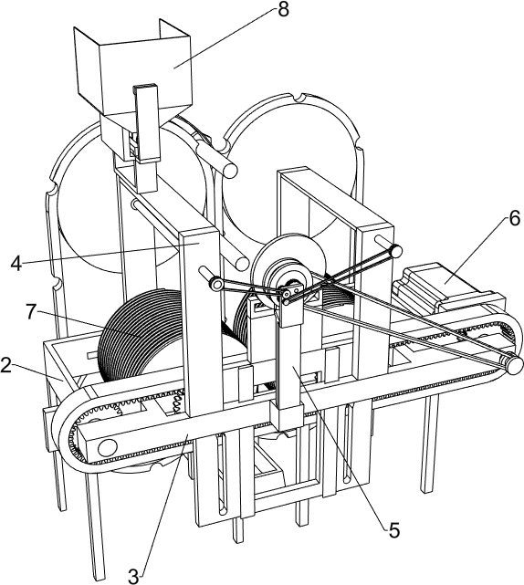
[0025] A kind of screw thread forming equipment, such as Figure 1-6 with Figure 8 As shown, it includes a support leg 1, a frame 2, a support plate 3, a support 4, a pillar 5, a drive assembly 6 and a working assembly 7, a plurality of support legs 1 are connected to the bottom of the frame 2, and a support plate 3 is connected to the rear side of the frame 2 , two brackets 4 are connected to the top of the support plate 3, and the two brackets 4 are left and right symmetrical. As for the component 6, the working component 7 is installed on the frame 2, and the driving component 6 is connected with the working component 7 in transmission.

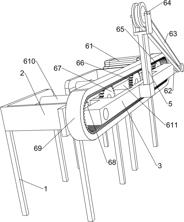
[0026] The driving assembly 6 includes a servo motor 61, a first rotating shaft 62, a first belt 63, a second rotating shaft 64, a first gear 65, a second gear 66, a third gear 67, a fourth gear 68, a timing belt 69, a Three rotating shafts 610 and the fourth rotating shaft 611, a servo motor 61 is installed on the left part of the fram...

Embodiment 2

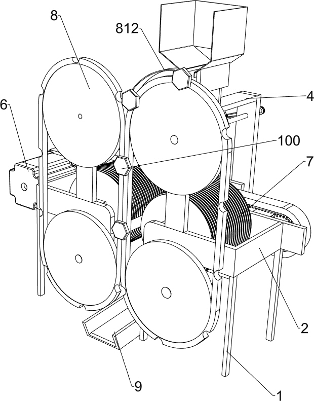
[0030] On the basis of Example 1, such as figure 1 , figure 2 , Image 6 with Figure 7 As shown, it also includes a feeding assembly 8, and the feeding assembly 8 includes a material box 81, a first rotating disk 82, a grooved belt 83, a sixth rotating shaft 84, a seventh rotating shaft 85, a second rotating disk 86, and a second incomplete gear 87, the sixth gear 88, the seventh gear 89, the second belt 810, the third belt 811 and the block 812, the front side of the top of the right side support 4 is connected with the material box 81, and the top of the right side support 4 is connected with the sixth rotating shaft in a rotational manner 84, the lower part of the front side of the right support 4 is rotatably connected with the first turntable 82, the front end of the sixth rotating shaft 84 is also connected with the first turntable 82, and the upper part of the left support 4 is rotatably connected with the seventh rotating shaft 85, the left support 4 The lower par...

Embodiment 3

[0033] On the basis of Example 2, such as figure 1 As shown, a collection tank 9 is also included, and a collection tank 9 is connected between the inner surfaces of the two legs 1 between the lower first turntable 82 and the lower second turntable 86, and the collection groove 9 is located on the lower side of the first turntable. 82 and below the second turntable 86 on the lower side, the collecting tank 9 is inclined to be set with the front low and the rear high.

[0034] The threaded screw rod 100 then falls into the collection tank 9, and then slides down into the collection frame through the collection tank 9, so that the screw rod 100 can be concentrated into the collection frame and prevent the screw rod 100 from scattering around.


PUM


Abstract

The invention relates to screw forming equipment, and particularly relates to screw thread forming equipment. The technical problem to be solved is how to provide the screw thread forming equipment that does not require manual placement and removal of a screw. In order to solve the technical problem, the screw thread forming equipment comprises a frame, a supporting plate, brackets, a supporting column, a driving assembly and a working assembly, wherein a plurality of supporting legs are connected to the end of the frame; the supporting plate is connected to one side of the frame; the end of the supporting plate is connected with the two brackets, and the brackets penetrate through the frame; one side of the supporting plate is connected with the supporting column; the driving assembly ismounted between the frame and the supporting plate; and the working assembly is mounted on the frame. According to the screw thread forming equipment, the working assembly and a feeding assembly can be driven by the driving assembly to work, the feeding assembly operates to convey the screw intermittently, the unthreaded screw is firstly conveyed into the working assembly, and the working assemblyoperates to thread the screw therein.

Description

technical field [0001] The invention relates to a screw forming device, in particular to a screw thread forming device. Background technique [0002] At present, the threading work of the screw is generally carried out manually. The unthreaded screw is manually placed between the two thread cutting barrels, and the screw is held, and then the threaded screw is pulled from between the two thread cutting barrels. Take out, go round and round, the worker needs to place and take out the screw repeatedly, so the workload of the worker is relatively large; and the worker relies on the feeling to place the screw, it is difficult to ensure that the position of the screw is consistent every time, resulting in errors in the produced screw. [0003] Therefore, there is an urgent need to develop a screw thread forming device that does not require manual placement and removal of the screw. Contents of the invention [0004] (1) Technical problems to be solved [0005] In order to ove...

Claims


Application Information

Patent Timeline
Patent Type & Authority Applications(China)
IPC IPC(8): B21H3/04B21H9/02
CPCB21H3/044B21H9/02
Inventor 黄德龙
Owner 南京力迅螺杆有限公司
Why Eureka
Try Eureka