Wire twisting device for elevator traction steel wire rope production

An elevator traction and steel wire rope technology, which is applied to auxiliary equipment for rope making, textile cables, transportation and packaging, etc., can solve the problems of inconvenient adjustment of strand density and number of strands, inability to grasp the traction tension, and easy breakage and damage of steel wires. , to achieve the effect of wide range of use, easy to promote and use, and easy to understand

Inactive Publication Date: 2020-11-24
湖州和通电梯部件有限公司
View PDF14 Cites 1 Cited by
  • Summary
  • Abstract
  • Description
  • Claims
  • Application Information

AI Technical Summary

Problems solved by technology

[0003] Most of the equipment used in the existing elevator traction wire rope twisting process has the problems of single function and complicated and difficult operation, and because the steel wire is generally in a winding state before twisting, the stress itself is relatively large, if no corresponding treatment , the steel wire rope is easy to rebound and deform after being skeined, which affects the quality of the skeined wire of the device. Most of these devices use the method of pulling the skeined wire, which is inconvenient to adjust the density and number of strands of the skeined wire. The use scenarios are limited and the practicability is low. Unable to grasp the pulling force during traction, the steel wire is easily broken and damaged after being subjected to too much pulling force, which will bring economic losses, and the actual use effect is poor

Method used


Image

  • Wire twisting device for elevator traction steel wire rope production
  • Wire twisting device for elevator traction steel wire rope production
  • Wire twisting device for elevator traction steel wire rope production

Examples


Embodiment Construction

[0026] The following will clearly and completely describe the technical solutions in the embodiments of the present invention with reference to the accompanying drawings in the embodiments of the present invention. Obviously, the described embodiments are only some, not all, embodiments of the present invention. Based on the embodiments of the present invention, all other embodiments obtained by persons of ordinary skill in the art without making creative efforts belong to the protection scope of the present invention.

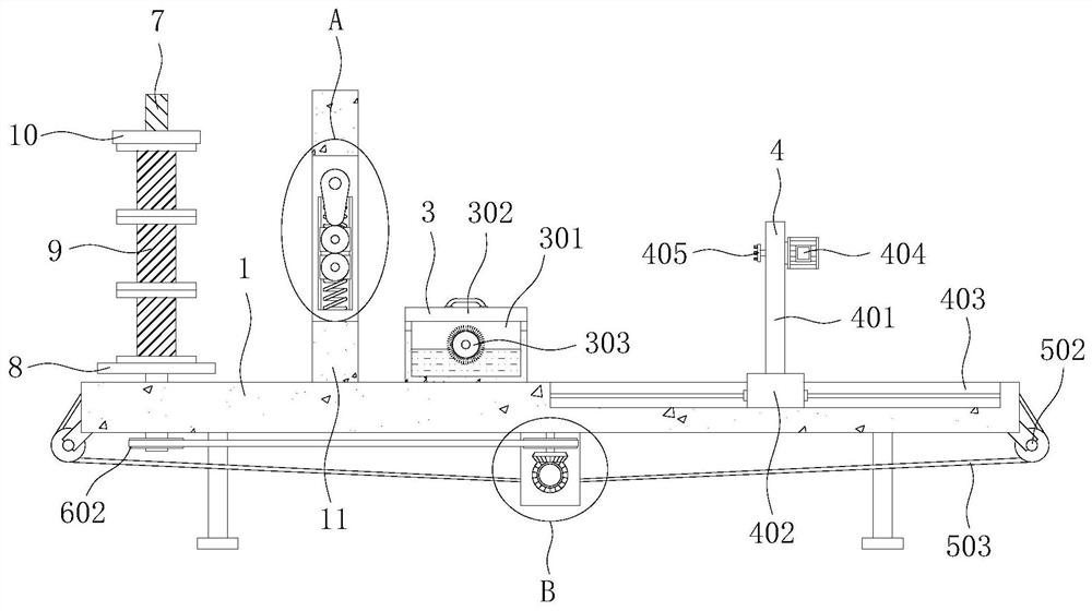
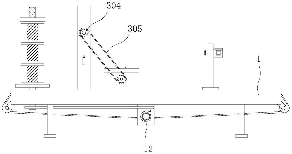
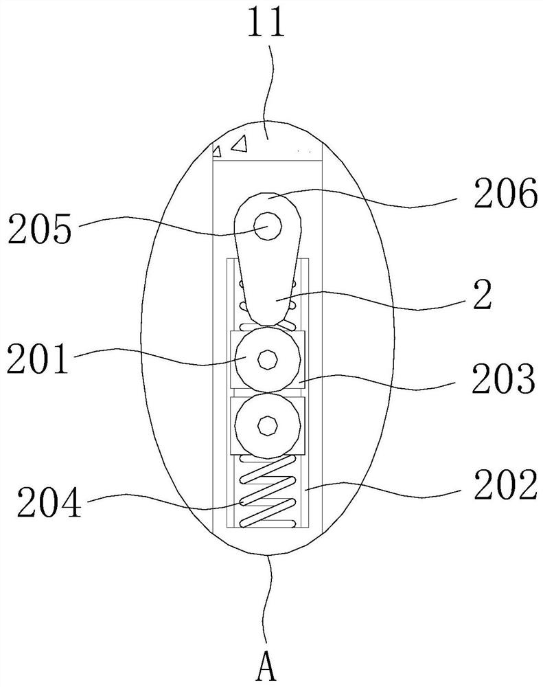
[0027] see Figure 1-6 , the present invention provides a technical solution: a stranding device for elevator traction wire rope production, including a workbench 1, on which a vibration aging mechanism 2, a lubrication mechanism 3, a stranding mechanism 4, a translation mechanism 5 and Transmission mechanism 6, threaded rod 7 is mounted on the top outer surface of workbench 1 for rotation, limit plate 8 is fixedly installed on the outer wall of threaded rod 7...


PUM


Abstract

The invention discloses a wire twisting device for elevator traction steel wire rope production, and relates to the technical field of elevator production and manufacturing. The wire twisting device for elevator traction steel wire rope production comprises a workbench, wherein a vibration aging mechanism, a lubricating mechanism, a wire twisting mechanism, a translation mechanism and a transmission mechanism are arranged on the workbench, a threaded rod is rotationally installed on the outer surface of the top of the workbench, a limiting disc is fixedly installed on the outer wall of the threaded rod, three sets of steel wire rollers and a set of fixing discs are installed on the outer wall of the threaded rod in a threaded mode, the three sets of steel wire rollers are attached to one another, and the fixing disc is located above the three sets of steel wire rollers. According to the wire twisting device for elevator traction steel wire rope production, stress left on a steel wire is reduced in a vibration mode before wire twisting operation, so that the steel wire is not prone to rebound and deformation in subsequent wire twisting operation, the wire twisting quality of the device is guaranteed, compared with a method for reducing stress by heating a workpiece, the device has the beneficial effects of being efficient, capable of saving energy and safe, and convenient popularization and application is facilitated.

Description

technical field [0001] The invention relates to the technical field of elevator manufacturing, in particular to a twisting device for elevator traction wire rope production. Background technique [0002] As the name suggests, the elevator wire rope is the wire rope used on the elevator, and it is the most widely used small passenger elevator. [0003] Most of the equipment used in the existing elevator traction wire rope twisting process has the problems of single function and complicated and difficult operation, and because the steel wire is generally in a winding state before twisting, the stress itself is relatively large, if no corresponding treatment , the steel wire rope is easy to rebound and deform after being skeined, which affects the quality of the skeined wire of the device. Most of these devices use the method of pulling the skeined wire, which is inconvenient to adjust the density and number of strands of the skeined wire. The use scenarios are limited and the ...

Claims


Application Information

Patent Timeline
Patent Type & Authority Applications(China)
IPC IPC(8): D07B7/02D07B7/10D07B7/12B66B7/06B66B7/12
CPCB66B7/06B66B7/1261D07B7/02D07B7/10D07B7/12
Inventor 吴伟炎
Owner 湖州和通电梯部件有限公司
Why Eureka
Try Eureka