DCT speed changer shifting fork gear engaging controlling method

A control method and transmission technology, applied in transmission control, clutches, components with teeth, etc., can solve the problems affecting the quality of shifting forks, and achieve the improvement of shifting quality and comfort, noise and vibration. Effect

Active Publication Date: 2020-11-24
CHONGQING TSINGSHAN IND
View PDF3 Cites 6 Cited by
  • Summary
  • Abstract
  • Description
  • Claims
  • Application Information

AI Technical Summary

Problems solved by technology

Analyzing the noise generated during the entire gear shifting process, there are generally noises generated by the coupling sleeve driving the gear ring to the synchronous position; after the synchronization is completed, the coupling sleeve passes through the gear ring to generate noise; and before the coupling sleeve enters the coupling ring gear, the coupling gear and coupling will occur The tooth tip of the ring gear collides with the tip to produce a secondary impact, or when the tooth surface of the combined gear

Method used


Image

  • DCT speed changer shifting fork gear engaging controlling method
  • DCT speed changer shifting fork gear engaging controlling method
  • DCT speed changer shifting fork gear engaging controlling method

Examples


Embodiment Construction

[0032] The present invention will be described in detail below in conjunction with the accompanying drawings.

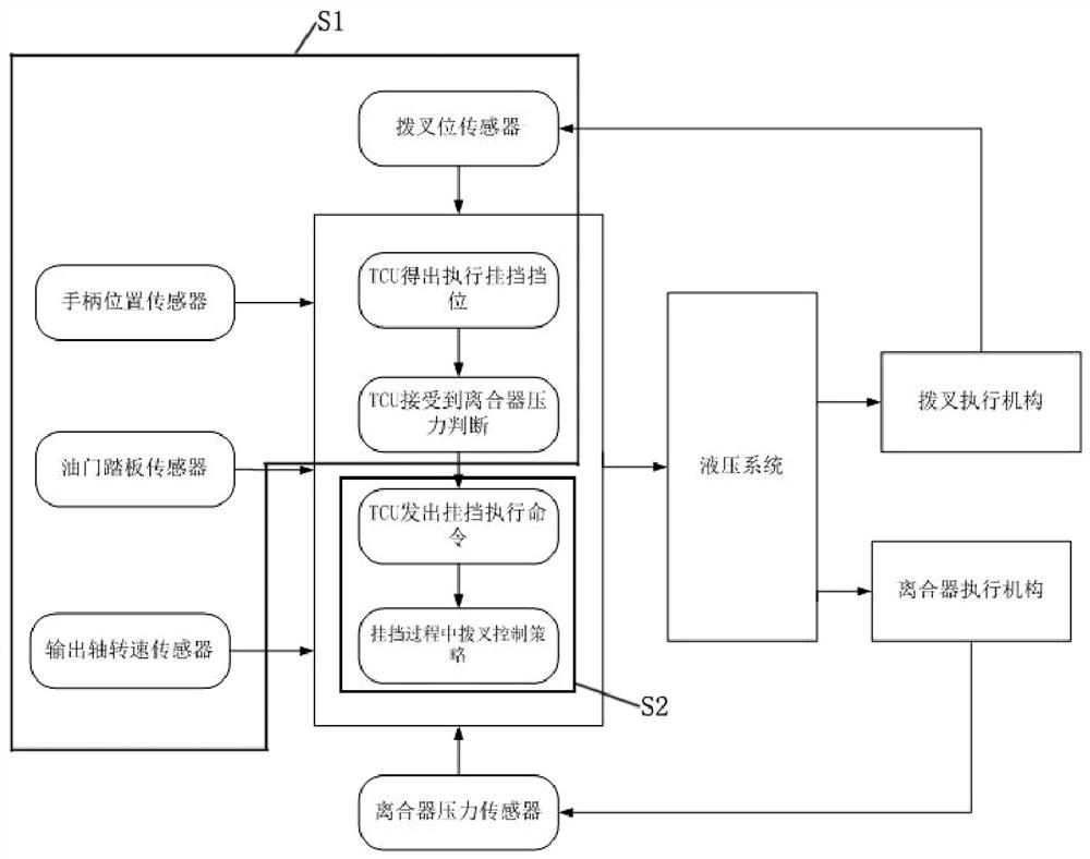
[0033] Such as figure 1 , DCT speed changer gear shifting control method, comprises the following steps:

[0034] S1, the TCU issues a command to execute the gear; before the TCU issues the command to execute the gear, the following preparations need to be made:

[0035] (1) Determine the gear to be engaged. The gear to be engaged is determined by the target gear and the pre-selected gear, and the target gear has priority over the pre-selected gear. The target gear is calculated by the output shaft speed, throttle opening and handle position, and the preselected gear is determined by the target gear and the throttle.

[0036] (2) Determine the gear sleeve speed of the gear synchronizer. The gear sleeve speed is calculated from the differential end speed, that is, the output end speed and speed ratio. The output end speed is calculated from the vehicle speed and tir...


PUM


Abstract

The invention discloses a DCT speed changer shifting fork gear engaging controlling method. The method comprises the following steps: S1: a TCU issues a gear engaging executing command; S2: the gear engaging executing command is processed by a gear engaging controlling strategy in the TCU; S21: in the first stage, under the action of shifting fork gear engaging force, a combined sleeve enables combined teeth to overcome acting force of a steel ball and therefore drives a ring gear to move from a vacant site to a synchronous starting point; S22: in the second stage, by exerting axial force on ashifting fork, and by eliminating revolving speed difference between a tooth ring and a tooth sleeve via the ring gear, the revolving speed difference is larger than a determined first threshold, andpreparation is made for the tooth sleeve to successfully push apart the ring gear and enter the tooth ring; S23: in the third stage, when the combined teeth penetrate through the ring gear and are ready to enter the tooth ring, the shifting fork and a clutch are matched with each other to ensure that the combined teeth can successfully enter the tooth ring; and S24: in the fourth stage, after thetooth sleeve penetrates through the tooth ring, when forward acting force is exerted on the shifting fork, reverse acting force is exerted at the same time, so the speed of the shifting fork is reduced to 0-0.0005m/s upon entering the tail end of the tooth ring and the tooth sleeve is prevented from striking the end surface of the tooth ring.

Description

technical field [0001] The patent of the present invention belongs to the field of automobile transmission control, and in particular relates to a method for controlling shift fork engagement of a DCT transmission. Background technique [0002] Dual-clutch transmission, as its name implies, has two clutches. On the basis of traditional manual transmission, two clutches, clutch actuators, shift actuators, electronic controllers and sensors are added. The electronic controller controls the shift actuator and clutch actuator. Instead of manually shifting gears manually, the operation of stepping on the clutch can realize automatic gear shifting of the transmission. The electronic control unit's precise control of the shift actuator is very important for the DCT transmission, which will affect the power, comfort and economy of the vehicle. [0003] At present, no matter whether the DCT transmission is used as an actuator to control the shifting fork through the motor or hydraul...

Claims


Application Information

Patent Timeline
IPC IPC(8): F16H61/16F16H61/04F16D48/10
CPCF16H61/16F16H61/04F16D48/10F16H2061/0474F16D2500/1107F16D2500/308F16D2500/50293
Inventor 李江华朱高华斯红路舒玉春曾开莲戴吕俊雅王毅谭章麒李洪
Owner CHONGQING TSINGSHAN IND
Why Eureka
Try Eureka