
Inspection and detection method for cast-in-place large-span concrete hollow slab

A detection method and hollow plate technology, applied in the direction of measuring devices, instruments, etc., can solve the problems of inability to meet the needs of engineering inspection and detection, inability to accurately judge whether the web is through, and the width of the "I" beam web is reduced. Achieve the effect of solving inspection and testing problems, good bearing performance, and simple operation

Inactive Publication Date: 2020-11-24
青岛市建筑工程质量检测中心有限公司
View PDF6 Cites 0 Cited by
  • Summary
  • Abstract
  • Description
  • Claims
  • Application Information

AI Technical Summary

Problems solved by technology

[0003] As a new technology, the construction technology is not very perfect, and some quality problems will inevitably occur in the construction of cast-in-place concrete hollow slabs, such as exposed ribs, holes, concrete cracks, floating of hollow tubes, horizontal displacement of hollow tubes, and possible floating of hollow tubes. The height of the upper flange of the "I"-shaped beam is reduced, and the horizontal displacement of the hollow tube leads to the reduction of the width of the "I"-shaped beam web. However, problems such as the width of the web and the height of the wing of the "I" girder cannot be found directly, and must be found through in-depth inspection. Due to the detection method of such problems, it is impossible to accurately judge whether the web is connected, which obviously cannot meet the needs of engineering inspection and detection.

Method used


Image

  • Inspection and detection method for cast-in-place large-span concrete hollow slab

Examples


Embodiment Construction

[0019] The following will clearly and completely describe the technical solutions in the embodiments of the present invention with reference to the accompanying drawings in the embodiments of the present invention. Obviously, the described embodiments are only some, not all, embodiments of the present invention.

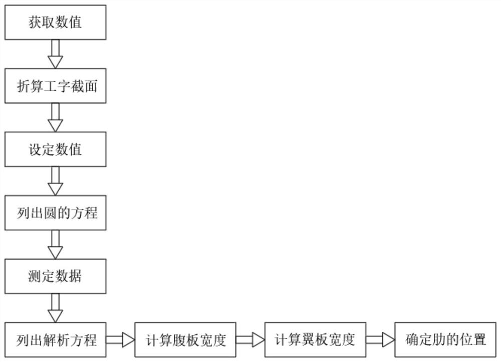
[0020] refer to figure 1 , an inspection and detection method for cast-in-situ large-span concrete hollow slabs, comprising the following steps:

[0021] S1: In the cast-in-place hollow slab member, calculate the plate width B of N holes intercepted in the direction of the parallel holes, calculate the circular hole part into a rectangle with equal area, equal centroid, and equal moment of inertia, and convert it into an "I"-shaped cross section;

[0022] S2: Assuming the diameter of the round hole is d, the width of the converted rectangle is b1, and the height is h1, then: the length L of the plate taken from the center of the rib in the direction perpendicular to ...


PUM


Abstract

The invention discloses an inspection and detection method for a cast-in-place large-span concrete hollow slab. The method comprises the following steps, calculating the plate width B of N holes intercepted in the direction parallel to the holes in a cast-in-place hollow plate component; calculating the circular hole part into a rectangle with equal area, equal centroid and equal inertia moment, converting into I-shaped cross section, setting the diameter of the circular hole to be d, the width of the converted rectangle to be b1, and the height to be h1, so that the plate length L perpendicular to the rib center distance in the plate hole direction is cut out in the direction perpendicular to the hole direction and simplified into the I-shaped section, the web thickness is equal to the rib width b, the wing width is equal to the rib center distance, and the height is the plate thickness h. The calculation result is simple, it is convenient for inspection and detection personnel to relatively accurately judge whether the web is through or not according to the derived numerical value, the construction quality of the interior of the cast-in-place hollow slab can be relatively accurately detected, the bearing performance of the structure is well reflected, and the inspection and detection problem is solved.

Description

technical field [0001] The invention relates to the technical field of concrete hollow slab detection, in particular to an inspection and detection method for cast-in-situ large-span concrete hollow slabs. Background technique [0002] The cast-in-place concrete hollow slab technology has the advantages of wide application range, especially for long-span floors, light weight, high rigidity, good shock resistance, good sound insulation effect, increased storey height and headroom, and reduced engineering cost. Used in large-span buildings such as exhibition halls and auditoriums, the hollow tube floor slab technology is a new formwork system technology for cast-in-place concrete slabs. Wall box, beams or concealed beams are set between columns, and concrete is poured without taking out the inner pipe, thus forming a cast-in-place hollow slab similar to a small "工" word dense rib beam. The role of the template. [0003] As a new technology, the construction technology is not...

Claims


Application Information

Patent Timeline
Patent Type & Authority Applications(China)
IPC IPC(8): G01B21/04G01B21/00
CPCG01B21/00G01B21/04
Inventor 刘效春
Owner 青岛市建筑工程质量检测中心有限公司
Learn More