High-pressure valve quick action test device

A technology of rapid action and test device, applied in the direction of mechanical valve testing, etc., can solve the problems of hard-to-be-tested valve support, low accuracy of test results, low valve stability, etc., to ensure stability, improve stability, and improve The effect of precision

Inactive Publication Date: 2020-11-24
六安一六八航空航天精密器件有限公司
View PDF6 Cites 0 Cited by
  • Summary
  • Abstract
  • Description
  • Claims
  • Application Information

AI Technical Summary

Problems solved by technology

[0003] When clamping the valve to be tested, the traditional valve quick action test equipment usually uses arc-shaped clamping blocks to directly clamp the two ends of the valve, and since the ends of the valve are generally provided with threads, the It is difficult for the inner surface to support the valve to be tested stably, which leads to the low stability of the valve during the test and the low accuracy of the test results

Method used


Image

  • High-pressure valve quick action test device
  • High-pressure valve quick action test device
  • High-pressure valve quick action test device

Examples


Embodiment 1

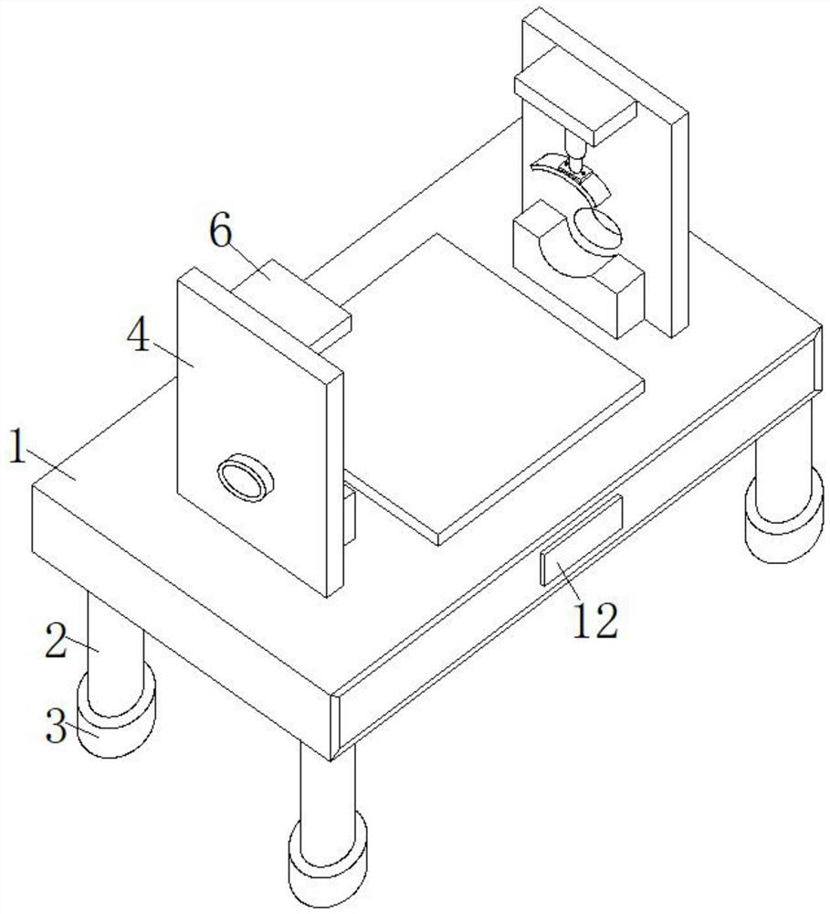
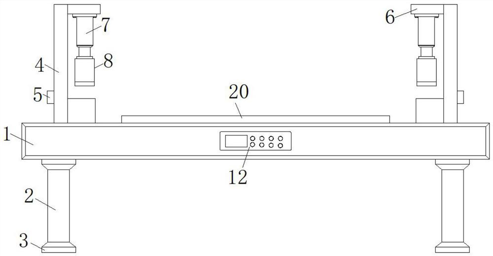
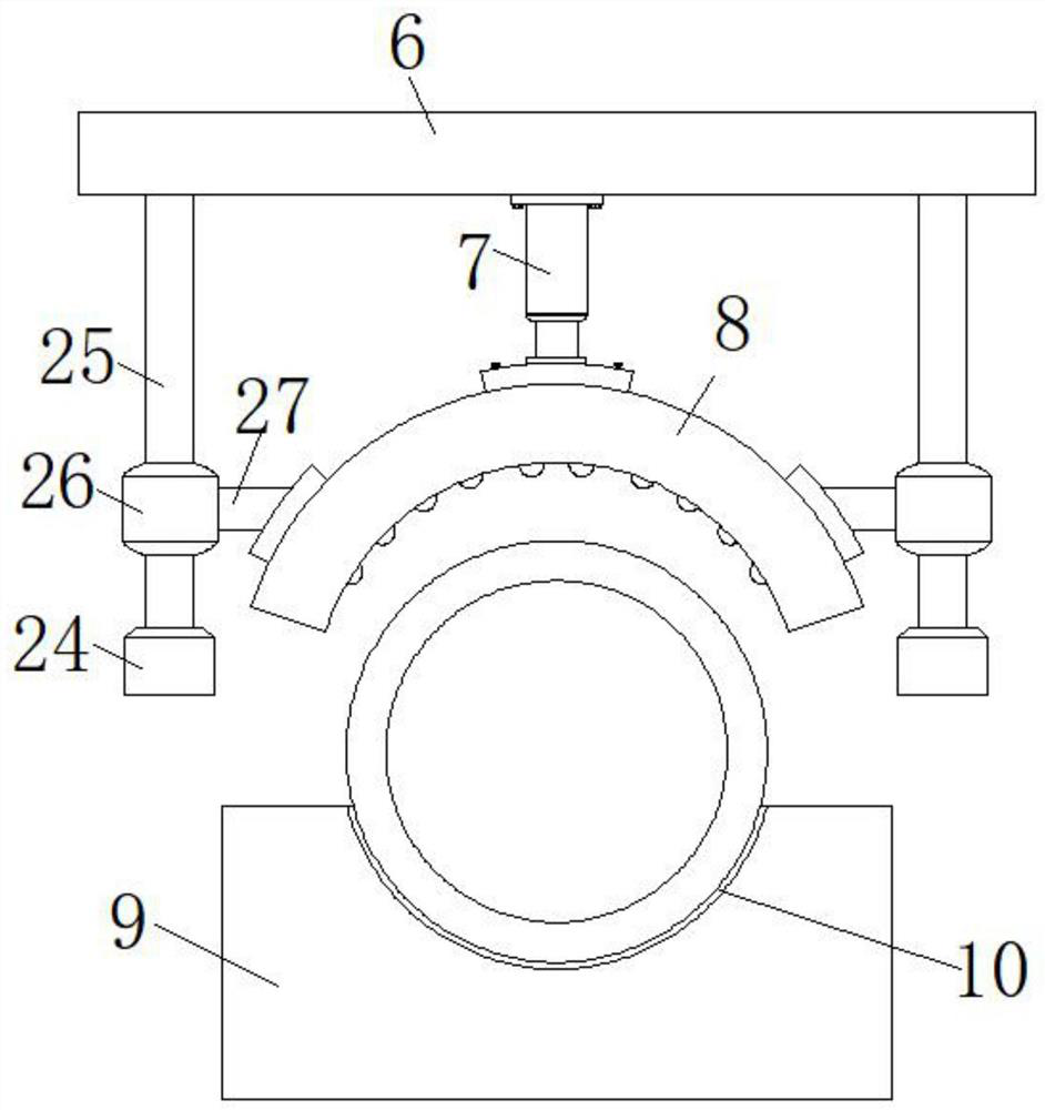
[0039] Such as Figure 1-6As shown, a high-pressure valve rapid action test device includes a test platform 1, and the bottom of the test platform 1 is fixedly equipped with evenly distributed support columns 2. The number of support columns 2 is four, and the four support columns 2 are evenly distributed. Distributed at the four corners of the bottom surface of the test platform 1, the bottom of the support column 2 is fixedly installed with a base 3, the base 3 is used for the connection between the support column 2 and the bottom surface, and the top surface of the test platform 1 is fixedly installed with two symmetrical The vertical boards 4, the sides of the two vertical boards 4 close to each other are provided with air ports 5, and the inner walls of the two air ports 5 are provided with O-shaped sealing rings, so as to increase the air inlets, air outlets and air outlets of external equipment. The tightness of the connection between the air ports 5, the two air ports ...

Embodiment 2

[0049] Such as Figure 7 As shown, the difference between this embodiment and Embodiment 1 is that: the top surface of the valve placement plate 20 is fixedly installed with evenly distributed second springs 29, and the end of the second spring 29 away from the valve placement plate 20 is fixedly installed with a pad A block 30, the side of the cushion block 30 away from the second spring 29 is fixedly installed with an anti-slip pad 31.

[0050] Using a plurality of pads 30 instead of the valve placement plate 20 to contact the valve to be tested can make the contact area between the pads 30 and the surface of the valve to be tested larger, and at the same time, the bottom of each pad 30 is provided with a second spring 29, It can ensure that each pad 30 can be in contact with the surface of the valve to be tested, thereby improving the support effect of the valve to be tested, further improving the stability of the valve to be tested during the test, and the anti-skid pad 31...


PUM


Abstract

The invention discloses a high-pressure valve quick action test device which comprises a test platform, and is characterized in that: two symmetrical vertical plates are fixedly mounted on the top surface of the test platform; transverse plates are fixedly installed on the side faces, close to each other, of the two vertical plates. An electric push rod is fixedly mounted on the bottom surface ofthe transverse plate; a clamping part is arranged at the output end of the electric push rod; two symmetrical base plates are fixedly mounted on the top surface of the test platform; the two side surfaces of the test platform are respectively provided with a PLC controller and a driving motor. A bidirectional threaded rod is fixedly mounted at the output end of the driving motor, two symmetrical threaded sleeves are in threaded connection with the outer surface of the bidirectional threaded rod, mounting rods are hinged to the tops of the two threaded sleeves, and a valve containing plate is hinged between the tops of the two mounting rods. According to the invention, multi-point contact clamping can be carried out on the arc-shaped clamping plate and the port of the valve, so that the stability of the valve to be tested during clamping is higher.

Description

technical field [0001] The invention belongs to the field of valve life test and relates to valve test equipment technology, in particular to a high-pressure valve quick action test device. Background technique [0002] Valves are pipeline fittings used to open and close pipelines, control flow direction, adjust and control the parameters of the conveying medium. According to their functions, they can be divided into shut-off valves, check valves, regulating valves, etc.; The control components have the functions of cut-off, regulation, flow diversion, reverse flow prevention, pressure stabilization, diversion or overflow pressure relief, etc., and are used in valves of fluid control systems, from the simplest cut-off valves to those used in extremely complex automatic control systems. There are various types and specifications of various valves. [0003] When clamping the valve to be tested, the traditional valve quick action test equipment usually uses arc-shaped clamping...

Claims


Application Information

Patent Timeline
Patent Type & Authority Applications(China)
IPC IPC(8): G01M13/003
CPCG01M13/003
Inventor 刘定查盛庞现贤
Owner 六安一六八航空航天精密器件有限公司
Why Eureka
Try Eureka