Movable multi-section linear light source CT imaging system and method

A linear light source and CT imaging technology, applied in the field of radiation imaging, can solve the problems of large noise and vibration, achieve the effect of reducing noise and vibration, meeting the needs of use, and fast scanning speed

Pending Publication Date: 2020-11-24
TSINGHUA UNIV
View PDF7 Cites 0 Cited by
  • Summary
  • Abstract
  • Description
  • Claims
  • Application Information

AI Technical Summary

Problems solved by technology

[0002] At present, CT imaging systems have played a vital role in the fields of medical treatment, industry, and security inspection. Traditional CT imaging systems are mostly circular or spiral orbit CTs. Circular or spiral orbit

Method used


Image

  • Movable multi-section linear light source CT imaging system and method
  • Movable multi-section linear light source CT imaging system and method

Examples


Embodiment 1

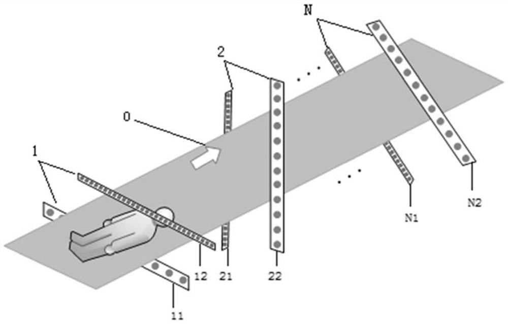
[0038] like figure 1 As shown, the movable multi-segment linear light source CT imaging system includes a plurality of scanning segments, namely the first scanning segment 1, the second scanning segment 2, ..., the Nth scanning segment N. Wherein, different scanning segments (ie, the first scanning segment 1 , the second scanning segment 2 , . . . , the Nth scanning segment N) are located in different planes. Each scanning section mainly includes a linear distributed light source array and a linear detector array, that is, the first scanning section 1 includes a first linear distributed light source array 11 and a first linear detector array 12, and the second scanning section 2 Including the second linear distributed light source array 21 and the second linear detector array 22, . . . , the Nth scanning segment N includes the Nth linear distributed light source array N1 and the Nth linear detector array N2. The linear distributed light source array and the linear detector ar...

Embodiment 2

[0041]The movable multi-segment linear light source CT imaging system includes a plurality of scanning segments, namely the first scanning segment, the second scanning segment, ..., the Nth scanning segment. Wherein, different scanning segments are located in different planes. Each scanning segment mainly includes a linear distributed light source array and a linear detector array, that is, the first scanning segment includes a first linear distributed light source array and a first linear detector array, and the second scanning segment includes a second linear The distributed light source array and the second linear detector array, ..., the Nth scanning segment includes the Nth linear distributed light source array and the Nth linear detector array. The linear distributed light source array and the linear detector array of each scanning segment are parallel to each other and distributed on both sides of the translation platform.

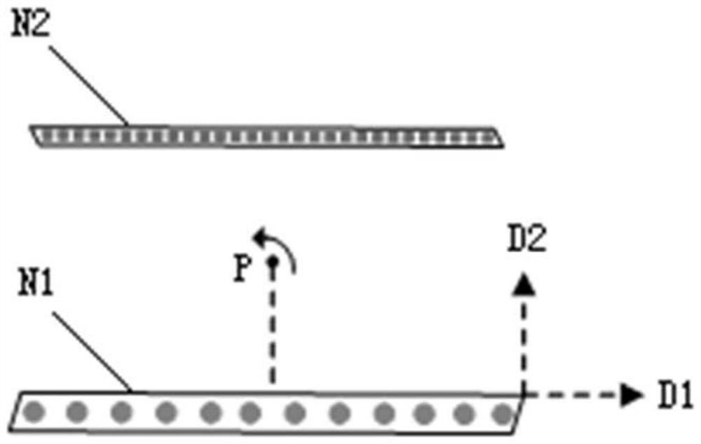
[0042] like figure 2 As shown, the scannin...


PUM


Abstract

The invention provides a movable multi-section linear light source CT imaging system and method. The linear light source CT imaging system comprises a plurality of movable scanning sections, each scanning section comprises a linear distributed light source array and a linear detector array, the linear distributed light source array is used for emitting rays, and the linear detector array is used for acquiring scanning projection data. The linear distributed light source array is a movable light source array and/or the linear detector array is a movable detector array. According to the movablemulti-section linear light source CT imaging system and method, the scanning view can be changed, the flexibility of the imaging system is improved, and the imaging system can adapt to different application scenes.

Description

technical field [0001] The invention relates to the technical field of radiation imaging, in particular to a movable multi-segment linear light source CT imaging system and method. Background technique [0002] At present, CT imaging systems have played a vital role in the fields of medical treatment, industry, and security inspection. Traditional CT imaging systems are mostly circular or spiral orbit CTs. Circular or spiral orbit CTs require the use of slip rings, noise and vibration The X-ray machine, high-voltage modules, detectors and other components have high mechanical strength requirements, and the safety and reliability need to be further improved. Contents of the invention [0003] (1) Technical problems to be solved [0004] In view of the above problems, the main purpose of the present invention is to provide a movable multi-segment linear light source CT imaging system and method, in order to at least partially solve at least one of the above-mentioned techni...

Claims


Application Information

Patent Timeline
IPC IPC(8): G01N23/046G01V5/00A61B6/03
CPCG01N23/046G01V5/005G01V5/0066A61B6/035G01N2223/3308G01N2223/33
Inventor 陈志强张丽高河伟张涛邢宇翔
Owner TSINGHUA UNIV
Why Eureka
Try Eureka