Eureka AIR delivers breakthrough ideas for toughest innovation challenges, trusted by R&D personnel around the world.

Driving shaft slip deflection angle checking method and driving shaft slip deflection angle checking system

A driving shaft and calibration technology, which is applied in special data processing applications, geometric CAD, design optimization/simulation, etc., can solve problems such as slippage distance, three-ball pin detachment, poor accuracy of simulation results, and influence on vehicle driving. To achieve the effect of accurate curve

Pending Publication Date: 2020-11-24
BEIJING ELECTRIC VEHICLE
View PDF5 Cites 3 Cited by
  • Summary
  • Abstract
  • Description
  • Claims
  • Application Information

AI Technical Summary

Problems solved by technology

In the related technology, only left and right wheel wheel jump and steering stroke are used as the drive in the motion analysis, resulting in a large gap between the calibration and the actual vehicle motion. The detachment from the moving joint shell will cause the vehicle to lose power; on the other hand, it will cause motion interference between the shaft of the drive shaft assembly and the surrounding parts, affecting the driving of the vehicle, and the accuracy of the simulation results is poor. , there is room for improvement

Method used


Image

  • Driving shaft slip deflection angle checking method and driving shaft slip deflection angle checking system
  • Driving shaft slip deflection angle checking method and driving shaft slip deflection angle checking system
  • Driving shaft slip deflection angle checking method and driving shaft slip deflection angle checking system

Examples


Embodiment Construction

[0024] Embodiments of the present application are described in detail below, examples of which are shown in the drawings, wherein the same or similar reference numerals denote the same or similar elements or elements having the same or similar functions throughout. The embodiments described below by referring to the figures are exemplary, and are only for explaining the present application, and should not be construed as limiting the present application.

[0025] In the prior art, the check of the slip angle of the drive shaft is only based on the check results, evaluated according to the empirical value and comprehensively determined by the actual vehicle road test verification, and there is a problem of insufficient design check or excessive design. Moreover, it is impossible to simulate the change of the total dynamic displacement of each working condition or a specific working condition on the basis of the existing drive, and the influence of the four-wheel parameters on th...


PUM


Abstract

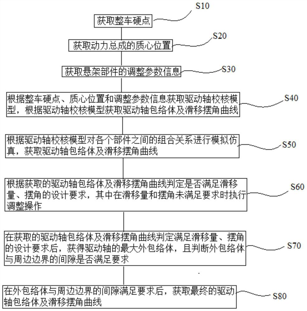
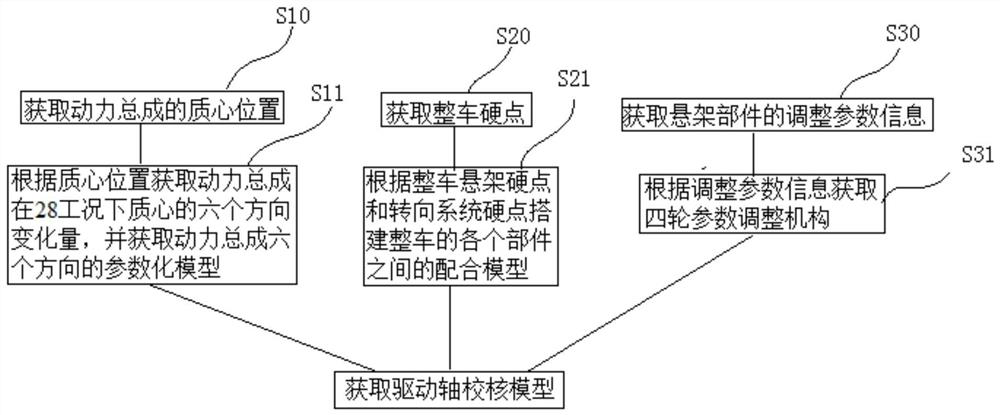
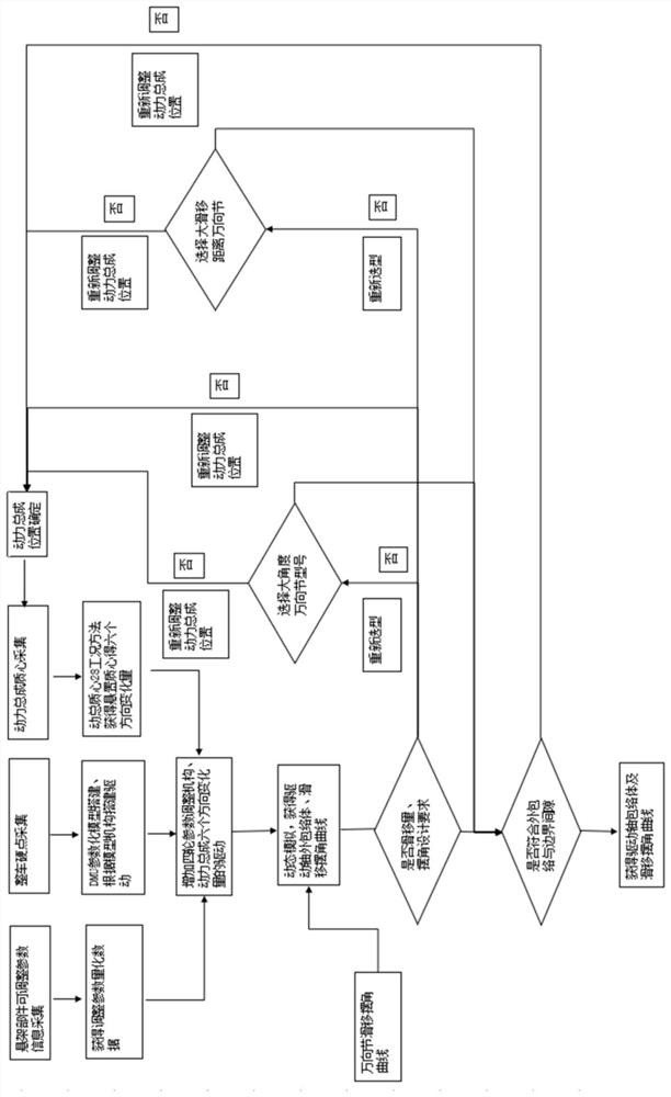
The invention discloses a method and a system for checking a slip deflection angle of a driving shaft. The method comprises the following steps of acquiring a hard point of a whole vehicle; obtainingthe mass center position of the power assembly; obtaining adjustment parameter information of the suspension component; and obtaining a driving shaft checking model according to the whole vehicle hardpoint, the mass center position and the adjustment parameter information, and obtaining a driving shaft envelope body and a slip swing angle curve according to the driving shaft checking model. The method for checking the slip deflection angle of the driving shaft is advantaged in that influence parameters such as the displacement of a power assembly and the adjustment amount of four-wheel parameters are constructed on a driving shaft checking model, the contribution and the influence degree of each parameter variable on the slip amount, the swing angle and the envelope of the driving shaft can be effectively analyzed, and meanwhile, specific analysis and checking can be carried out in combination with actual vehicle arrangement and parameters, so a problem of insufficient design or excessive design caused by design and checking of all vehicle types only depending on empirical values is avoided, and the obtained drive shaft envelope body and slip swing angle curve are more accurate.

Description

technical field [0001] The present application relates to the technical field of vehicle manufacturing, in particular to a method for checking the slip angle of a drive shaft and a system for checking the slip angle of a drive shaft suitable for the checking method. Background technique [0002] At present, the constant velocity drive shaft assembly is checking the maximum angle between the fixed joint and the moving joint, the sliding distance of the moving joint, and the clearance between the outer envelope and the surrounding boundary through DMU for motion analysis. In the related technology, only left and right wheel wheel jump and steering stroke are used as the drive in the motion analysis, resulting in a large gap between the calibration and the actual vehicle motion. The detachment from the moving joint shell will cause the vehicle to lose power; on the other hand, it will cause motion interference between the shaft of the drive shaft assembly and the surrounding pa...

Claims


Application Information

Patent Timeline
Patent Type & Authority Applications(China)
IPC IPC(8): G06F30/15G06F30/20
CPCG06F30/15G06F30/20
Inventor 王庚川李波张浩李鹏飞田常浩李若松
Owner BEIJING ELECTRIC VEHICLE
Why Eureka
Eureka Blog
Learn More