Mobile phone battery side edge adhesive tape pasting equipment
A mobile phone battery and glue sticking technology, which is applied to batteries, battery assembly machines, secondary battery manufacturing, etc., can solve the problems of unstable battery quality, cumbersome glue sticking steps, uneven battery surface, etc., and shorten the circulation time , Reduce production costs and improve efficiency
- Summary
- Abstract
- Description
- Claims
- Application Information
AI Technical Summary
Problems solved by technology
Method used
Image

Examples
Embodiment Construction
[0039]The present invention will be further described below in conjunction with accompanying drawing:
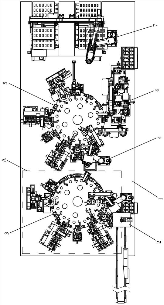
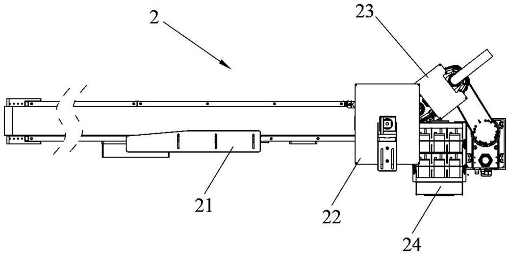
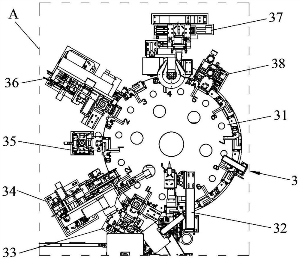
[0040] Such as figure 1 Shown: a mobile phone battery side gluing equipment, including a workbench 1 and a feeding mechanism 2 installed on the workbench 1, a first gluing mechanism 3, a transfer mechanism 4, a second gluing mechanism 5, a heating Press mechanism 6 and blanking mechanism 7;
[0041] The first gluing mechanism 3 and the second gluing mechanism 5 are respectively arranged on both sides of the workbench 1, the feeding mechanism 2 mechanism is arranged on the side of the first gluing mechanism 3, and the material transfer mechanism 4 is arranged on the first gluing mechanism. Between the gluing mechanism 3 and the second gluing mechanism 5, the hot pressing mechanism 6 and the blanking mechanism 7 are arranged on the side of the second gluing mechanism 5, and the second gluing mechanism 5 and the first gluing mechanism 3 have the same structure, The first glui...
PUM
 Abstract
Description
Claims
Application Information
 - R&D
- Intellectual Property
- Life Sciences
- Materials
- Tech Scout
- Unparalleled Data Quality
- Higher Quality Content
- 60% Fewer Hallucinations
Browse by: Latest US Patents, China's latest patents, Technical Efficacy Thesaurus, Application Domain, Technology Topic, Popular Technical Reports.
© 2025 PatSnap. All rights reserved.Legal|Privacy policy|Modern Slavery Act Transparency Statement|Sitemap|About US| Contact US: help@patsnap.com