
Fastening mechanism of high-voltage power sheath pipe and using method thereof

A technology of high-voltage electric power and fastening mechanism, applied in the direction of electrical components, etc., can solve the problems of damage to the sheath tube, uncontrollable locking force, shaking, etc., and achieve the effect of reliable heat dissipation

Inactive Publication Date: 2020-11-24
安徽玉发塑业有限公司
View PDF1 Cites 0 Cited by
  • Summary
  • Abstract
  • Description
  • Claims
  • Application Information

AI Technical Summary

Problems solved by technology

[0004] The above-mentioned patent has the following disadvantages: it uses the motor to drive the screw, and then cooperates with the corresponding slider to lock the pipeline. When the threaded connection drives the slider to lock, the locking force cannot be controlled, and due to the way the threads engage, its The locking torque is different each time, and there are no rules to follow. If the locking force is too small, it will cause shaking. If the locking force is large, it will cause damage to the sheath tube.

Method used


Image

  • Fastening mechanism of high-voltage power sheath pipe and using method thereof
  • Fastening mechanism of high-voltage power sheath pipe and using method thereof
  • Fastening mechanism of high-voltage power sheath pipe and using method thereof

Examples


Embodiment 1

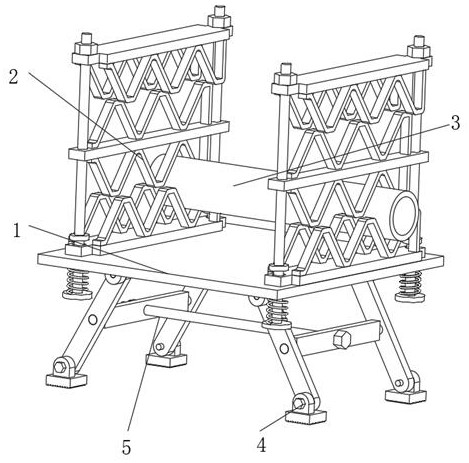
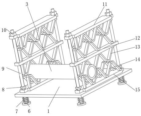
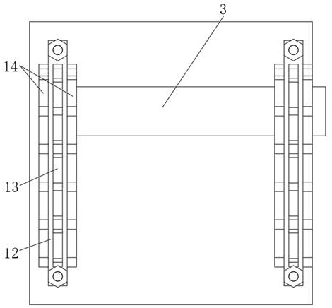
[0042] A fastening mechanism for high-voltage power sheath pipes, such as figure 1 , 2 As shown, it includes a table top 1, a flexible fastening assembly 2 arranged on the top of the table 1, and a sheath pipe body 3 fastened by the flexible fastening assembly 2. The flexible fastening assembly 2 includes a first bracket 13 and a second bracket 14. The top outer wall of the table 1 close to the locking rod 9 is fixed with a bottom plate 15 by bolts, wherein two second brackets 14 are installed in a linear array on the top outer wall of the bottom plate 15, and the four corners of the table 1 The inner walls are all slidably connected with locking rods 9, the outer walls of the locking rods 9 are respectively provided with a middle plate 12 and a top plate 11, and the other two second brackets 14 are installed in a linear array on the bottom outer wall of the top plate 11 , the two first brackets 13 are respectively fixedly installed on the top and bottom outer walls of the mi...

Embodiment 2

[0047] A fastening mechanism for high-voltage power sheath pipes, such as figure 1 , 4 As shown, in order to solve the problem of height adjustment; this embodiment makes the following improvements on the basis of embodiment 1: it also includes a second adjustment assembly 5, which includes four mutually symmetrical legs 18 and used in conjunction with The second adjusting screw 23 and the second adjusting nut 24, the bottom outer wall of the table top 1 is welded with the first hinge block 16, and the legs 18 are connected to the outer wall of the first hinge block 16 through the first hinge rod 17 in rotation , the inner walls of the two adjacent legs 18 are rotatably connected with adjustment plates 26 through the second hinge rod 25, the inner walls of the two adjustment plates 26 are provided with through holes, and the second adjustment screw 23 is wrapped On the inner wall of the through hole, the second adjusting nut 24 is threadedly connected to the outer wall of the...

Embodiment 3

[0050] A fastening mechanism for high-voltage power sheath pipes, such as figure 1 , 4 As shown, in order to solve the problem of height adjustment; this embodiment makes the following improvements on the basis of embodiment 2: it also includes a first adjustment assembly 4, which includes a first adjustment screw 20 and an anti-skid pad 21, The top outer wall of the anti-skid pad 21 is welded with a second hinge block 19, and the second hinge block 19 and the inner wall of the leg 18 are provided with adjustment holes, and the first adjustment screw 20 is arranged in the two adjustment holes. The inner wall on the other side of the first adjusting screw 20 is threadedly connected with a first adjusting nut 22; when the height is adjusted, the leg 18 rotates and the contact surface with the ground changes, which may cause Shaking, etc., and by being provided with the first adjustment assembly 4, before adjusting the height, the first adjustment nut 22 is loosened, so that the...


PUM


Abstract

The invention discloses a fastening mechanism of a high-voltage power sheath pipe and a using method thereof, and relates to the technical field of cable protection auxiliary equipment. in order to solve the problem that a sheath pipe body is damaged, the fastening mechanism of the high-voltage power sheath sleeve specifically comprises a table top, a flexible fastening assembly arranged at the top of the table top and a sheath pipe body fastened through the flexible fastening assembly. The flexible fastening assembly comprises a first support and second supports, a bottom plate is fixed to the outer wall of the top, close to the locking rod, of the table top through bolts, and the two second supports are installed on the outer wall of the top of the bottom plate in a linear array mode. According to the invention, the locking spring is arranged. The locking force on the sheath pipe body is directly related to the tightening degree of the locking nut, namely the compression amount of the locking spring, the locking force on the sheath pipe body can be controlled through the tightening degree of the locking nut, the sheath pipe body is relatively flexibly fixed through the whole flexible fastening assembly, and the sheath pipe body cannot be damaged.

Description

technical field [0001] The invention relates to the technical field of cable protection auxiliary equipment, in particular to a fastening mechanism for a high-voltage electric sheath tube and a method for using the same. Background technique [0002] In the actual laying of cables, in order to protect the cables and uniformly protect multiple cables, it is necessary to cover the cables with sheath tubes. After the cables are covered with sheath tubes, for some non-buried cables, the Corresponding fastening devices are needed to fasten and position the cable sheath tube. In some areas where the power transmission is relatively concentrated and the cable distribution is relatively dense, in order to classify and split and ensure heat dissipation, all wire harnesses need to be divided into categories and paths. For different strands, put sheath tubes on different strands of cables, and finally fix the sheath tubes uniformly. [0003] After searching, the Chinese patent publica...

Claims


Application Information

Patent Timeline
Patent Type & Authority Applications(China)
IPC IPC(8): H02G3/04H02G3/03
CPCH02G3/03H02G3/0425H02G3/0456H02G3/0481
Inventor 舒峰舒玉法王克兰姚艳芳张宗运王祖林张世兵胡华兆郭涛季琨马勇
Owner 安徽玉发塑业有限公司
Learn More