
Transformer substation switch control system and transformer substation switch control method

A switch control system and switch control technology, applied in information technology support systems, electrical components, circuit devices, etc., to achieve the effects of simple debugging, simplified circuits, and reduced probability of circuit errors

Active Publication Date: 2020-11-24
GUANGDONG POWER GRID CO LTD +1
View PDF5 Cites 0 Cited by
  • Summary
  • Abstract
  • Description
  • Claims
  • Application Information

AI Technical Summary

Problems solved by technology

[0008] The embodiment of the present invention provides a substation switch control system and a substation switch control method to solve the problems existing in the closing control mode of the substation side outlet switch in the prior art

Method used


Image

  • Transformer substation switch control system and transformer substation switch control method
  • Transformer substation switch control system and transformer substation switch control method
  • Transformer substation switch control system and transformer substation switch control method

Examples


Embodiment Construction

[0058] The present invention will be further described in detail below in conjunction with the accompanying drawings and embodiments. It should be understood that the specific embodiments described here are only used to explain the present invention, but not to limit the present invention. In addition, it should be noted that, for the convenience of description, only some structures related to the present invention are shown in the drawings but not all structures.

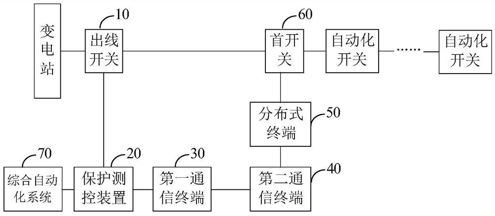
[0059] figure 1 A schematic structural diagram of a substation switch control system provided by an embodiment of the present invention, the substation switch control system is used to implement the substation switch control method of the embodiment of the present invention to control the closing of the outlet switch of the substation. Such as figure 1 As shown, the substation switch control system of the embodiment of the present invention includes: a substation outgoing line switch 10, a protection measurement ...


PUM


Abstract

The embodiment of the invention discloses a transformer substation switch control system and a transformer substation switch control method. The transformer substation switch control system comprisesa transformer substation outgoing line switch, a protection measurement and control device connected with the outgoing line switch, a first communication terminal connected with the protection measurement and control device, and a second communication terminal connected with the first communication terminal and a distributed terminal on the head switch side. The distributed terminal collects faultinformation and action information of a head switch and sends the fault information and the action information to the protection measurement and control device through the first communication terminal and the second communication terminal; the protection measurement and control device determines whether to generate a closing instruction to control reclosing of the outgoing line switch according to the fault information and the action information. A distributed terminal and a secondary circuit for acquiring current and voltage are not required to be mounted on the outgoing line switch side; the system is simple in debugging, simplifies a circuit, reduces the error probability, is small in communication data size, is not high in requirements for the communication rate and quality, still achieves the switching-on or switching-off of the outgoing line switch through the protection measurement and control device at the side of the outgoing line switch, is accurate in responsibility confirmation, and is clear in management interface.

Description

technical field [0001] The embodiments of the present invention relate to the technical field of power distribution, and in particular to a substation switch control system and a substation switch control method. Background technique [0002] Feeder Automation (FA, Feeder Automation) refers to the use of automated devices or systems to monitor the operating status of distribution lines to detect line faults in time, and quickly diagnose faulty areas to isolate faulty areas and restore power to non-faulty areas. At present, intelligent distributed feeder automation is divided into fast-acting and slow-acting distributed feeder automation. [0003] In the slow-moving intelligent distributed automation, the 10kV outlet switch of the substation belongs to the substation system and does not have the distributed feeder automation function. In this way, the distributed terminal on the outlet switch side directly controls the outlet switch, or forwards the control command and the p...

Claims


Application Information

Patent Timeline
Patent Type & Authority Applications(China)
IPC IPC(8): H02J13/00
CPCH02J13/00026H02J13/00016H02J13/00017H02J13/0004H02J2213/10Y04S40/124Y04S40/126Y02E60/00
Inventor 罗滨成新苗黄斌王玉姬郑淑仪郑继南李俊松潘靖
Owner GUANGDONG POWER GRID CO LTD
Learn More