Circuit including configuration terminal and method

A circuit and terminal technology, applied in circuits, logic circuits, circuit devices, etc., can solve problems such as increased current consumption and violation of RF specifications

Pending Publication Date: 2020-11-24
INFINEON TECH AG
View PDF0 Cites 0 Cited by
  • Summary
  • Abstract
  • Description
  • Claims
  • Application Information

AI Technical Summary

Problems solved by technology

This is caused at least in part by the rectification of the RF signal at the diodes of the ESD circuit, and may result in higher order harmonics
This in turn can lead to RF specification violations and the rectified RF signal also leads to increased current consumption

Method used


Image

  • Circuit including configuration terminal and method
  • Circuit including configuration terminal and method
  • Circuit including configuration terminal and method

Examples


Embodiment Construction

[0020] Hereinafter, various embodiments will be described in detail with reference to the accompanying drawings. These embodiments should be considered as illustrative examples only, and should not be construed as restrictive. For example, while embodiments may be described as including many features, in other embodiments some of these features may be omitted or may be replaced by alternative features. In addition to the features explicitly shown in the drawings or described herein, additional features may be provided, for example as provided in conventional circuits.

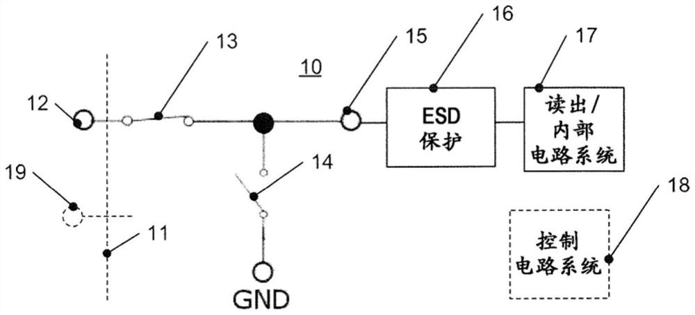
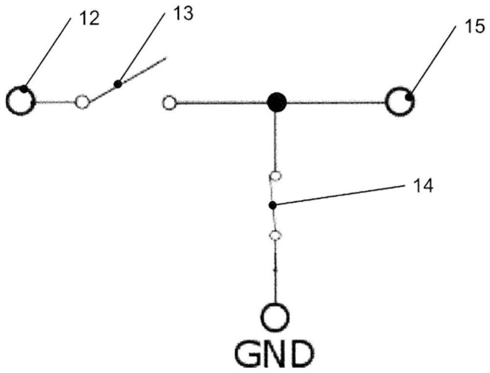
[0021] For example, the embodiments described below relate to the coupling and decoupling of configuration terminals to other parts of the circuit, such as internal nodes. In addition to the described couplings and decouplings and the circuitry associated therewith, in some embodiments circuits may be implemented in a conventional manner and may include additional terminals, additional circuit components, etc....


PUM


Abstract

Embodiments of the present disclosure generally relate to circuits and methods including configuration terminals. Circuits and methods are provided, where a configuration terminal (12) of the circuit(10) is coupled to an internal node (15) during a configuration phase and decoupled from the internal node (15) during normal operation.

Description

technical field [0001] The present application relates to circuits comprising configuration terminals and to corresponding methods. Background technique [0002] Electronic circuits include terminals for communicating with other entities, for example to receive supply voltages, receive input signals or output output signals. Where the circuit is provided in a package, such terminals may be provided as pins of the package. [0003] Such terminals, such as pins, are typically protected against electrostatic discharge (ESD) by ESD protection circuitry, which may be implemented by diodes coupled between the respective terminal and a reference potential. In normal operation, diodes are non-conductive. In the event of an electrostatic discharge resulting in a high voltage, the diode becomes conductive, thus bringing the charge generated by the electrostatic discharge down to a reference potential. [0004] One type of terminal is a configuration terminal for configuring a circu...

Claims


Application Information

Patent Timeline
Patent Type & Authority Applications(China)
IPC IPC(8): H03K19/0175H03K19/0185H03K17/687H03K19/00H03K19/003
CPCH03K19/017545H03K19/018507H03K17/687H03K19/0013H03K19/00315H03K19/00361H03K19/00338H01L27/0292H02H9/046H01L27/0255H01L27/0266H05K9/0067H05K9/00H01L27/02
Inventor W·巴卡尔斯基A·贝尼施
Owner INFINEON TECH AG
Why Eureka
Try Eureka