Terminal resistance circuit, chip and chip communication device

A terminal resistance and resistance circuit technology, which is applied to logic circuits using specific components, logic circuits using basic logic circuit components, electronic switches, etc., can solve problems such as abnormal operation of the chip system, chip conduction, short circuit, etc., and achieve improvement The effect of stability

Active Publication Date: 2021-04-30
SHENZHEN PANGO MICROSYST CO LTD
View PDF11 Cites 0 Cited by
  • Summary
  • Abstract
  • Description
  • Claims
  • Application Information

AI Technical Summary

Problems solved by technology

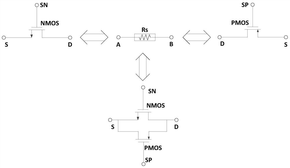
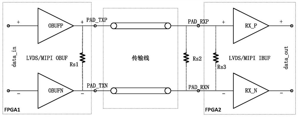
[0003] However, at present, the chip usually has a terminal resistance between the two ends of the high-speed differential I / O pair, which will be turned on when the chip is powered on, which will cause a short circuit at the two ends of the high-speed differential I / O pair of the chip, causing the chip The problem of abnormal system operation

Method used


Image

  • Terminal resistance circuit, chip and chip communication device
  • Terminal resistance circuit, chip and chip communication device
  • Terminal resistance circuit, chip and chip communication device

Examples


Embodiment Construction

[0019] In order to make the purposes, technical solutions and advantages of the embodiments of the present application clearer, the technical solutions in the embodiments of the present application will be clearly and completely described below in conjunction with the drawings in the embodiments of the present application. Obviously, the described embodiments It is a part of the embodiments of this application, not all of them. The components of the embodiments of the application generally described and illustrated in the figures herein may be arranged and designed in a variety of different configurations.

[0020] Accordingly, the following detailed description of the embodiments of the application provided in the accompanying drawings is not intended to limit the scope of the claimed application, but merely represents selected embodiments of the application. Based on the embodiments in this application, all other embodiments obtained by persons of ordinary skill in the art w...


PUM


Abstract

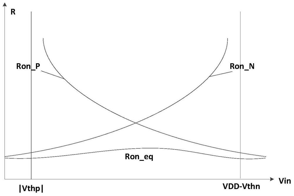
The embodiment of the invention discloses a terminal resistance circuit, a chip and a chip communication device, and relates to the technical field of semiconductor integrated circuits. The terminal resistance circuit is applied to a high-speed differential I / O pair of a chip, the high-speed differential I / O pair comprises a first interface and a second interface, the terminal resistance circuit comprises two resistance circuits and a control circuit, one ends of the two resistance circuits are electrically connected with the first interface after the two resistance circuits are connected in series, and the other ends of the two resistance circuits are electrically connected with the second interface after the two resistance circuits are connected in series, a target node is arranged on the wire between the two resistance circuits, and the two resistance circuits are symmetrically arranged relative to the target node; and the control circuit is electrically connected with the two resistance circuits respectively and is used for controlling the two resistance circuits to be in an off state in the power-on process of the chip. According to the invention, the problem of abnormal system operation caused by short circuit of the two I / Os in the power-on process of the chip can be avoided, and the working stability of the chip is improved.

Description

technical field [0001] The present application relates to the technical field of semiconductor integrated circuits, and more specifically, to a terminal resistance circuit, a chip, and a chip communication device. Background technique [0002] With the rapid development of integrated circuits, Field Programmable Gate Array (Field Programmable GateArray, FPGA) chip, as a programmable logic device, has gradually evolved from a peripheral device of electronic design to a core of digital system in just over 20 years. At the core, along with the advancement of semiconductor process technology, the design technology of FPGA chips has also achieved leapfrog development and breakthroughs. Due to the characteristics of high density, high security, low power consumption, low cost, system integration, and dynamic reconfigurability, FPGA chips have been widely used in communication, aerospace, consumer electronics and other fields. [0003] However, at present, the chip usually has a t...

Claims


Application Information

Patent Timeline
Patent Type & Authority Applications(China)
IPC IPC(8): G05B19/042
CPCG05B19/0423G05B2219/21109H03K19/173G06F13/20H03K17/6874H03K17/223G06F2213/40H03K17/6872
Inventor 张千文梁爱梅温长清王齐尉
Owner SHENZHEN PANGO MICROSYST CO LTD
Why Eureka
Try Eureka