Rotor and rotating electric machine with rotor
A technology for rotating electrical machines and rotors, which is used in motors, electric vehicles, magnetic circuit rotating parts, etc., can solve the problems of high supply risk, scarcity of heavy rare earths, uneven distribution of production areas, and achieve the effect of improving the anti-demagnetization force.
- Summary
- Abstract
- Description
- Claims
- Application Information
AI Technical Summary
Problems solved by technology
Method used
Image


Examples
Embodiment 1
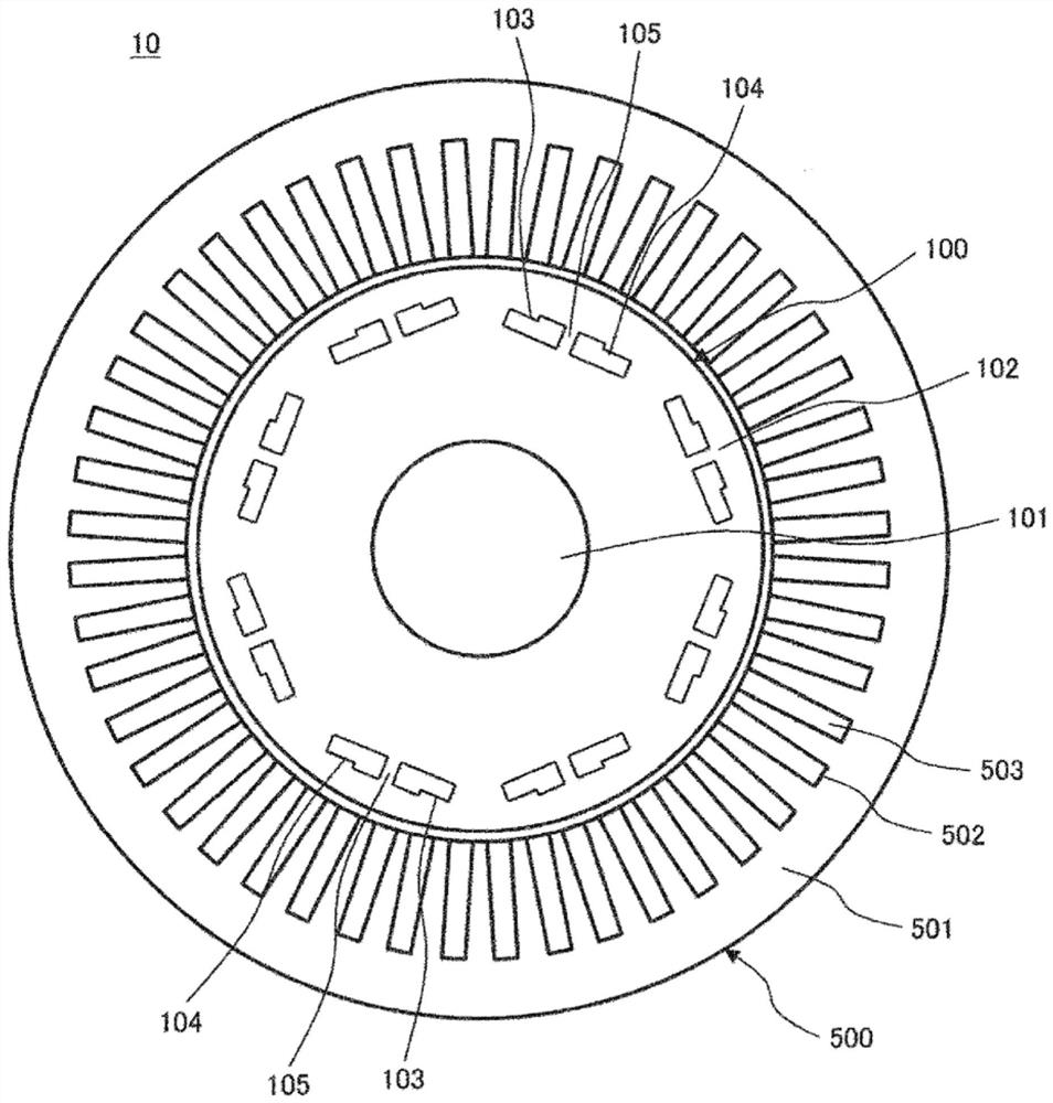
[0024] A first embodiment of the present invention will be described. figure 1 It is a cross-sectional view of the rotating electrical machine according to the first embodiment of the present invention cut in the radial direction. The rotating electric machine 10 includes a rotor 100 , a shaft 101 fixed to the rotor 100 , and a stator 500 arranged around the rotor 100 . The rotating electrical machine 10 is mounted on vehicles such as a hybrid car or an electric car, for example, and has both a function as a motor that rotates the shaft 101 by being supplied with electric power and a function as a generator that generates electricity by the rotation of the shaft 101, and can be Each function can be switched and used according to the driving state.
[0025] The shaft 101 is a rod-shaped member penetrating through the center of the rotor 100 , is fixed to the rotor 100 , and rotates integrally with the rotor 100 . The rotor 100 includes a rotor core 102 formed by laminating a ...
Embodiment 2
[0048] Next, use Figure 4 as well as Figure 5 , the second embodiment of the present invention will be described. Figure 4 It is a partial enlarged view of the magnet housing part of the second embodiment of the present invention, showing the configuration of one pole in the rotor of the rotating electric machine. Figure 5 for Figure 4 Partial enlarged view of one side of the magnet housing in .
[0049] Permanent magnets 210 , 211 are housed in magnet housing portions 203 , 204 formed in rotor core 102 , respectively. A bridge 205 is provided between the magnet storage parts 203 and 204 . A virtual centerline 206 is provided at the center of the bridge 205 . The center line 206 is a line passing through the rotation center of the shaft 101 (rotor 100). The magnet housing portions 203 and 204 are formed line-symmetrically with respect to the center line 206 .
[0050] Surfaces 213a and 213b on the outer peripheral side of rotor core 102 in magnet accommodating port...
Embodiment 3
[0077] Next, use Figure 6 , the third embodiment of the present invention will be described. Figure 6 It is a partially enlarged view of a magnet housing portion according to a third embodiment of the present invention, showing the configuration of one pole of a rotor of a rotating electric machine. The difference from the second embodiment lies in the size of the magnet housing part 203a, the magnet housing part 204a, and the sizes of the permanent magnets 210a and 211a housed in them. The other configurations are the same as those of the second embodiment, so detailed descriptions will be omitted below.
[0078] exist Figure 6 Here, the dimensions (magnitude) in the direction of the center line 206 of the magnet housing portions 203a, 203b and the magnet housing portions 204a, 204b are set to be the same. In addition, the dimensions (magnitudes) in the direction perpendicular to the center line 206 of these permanent magnets are also set to be the same. Along with thi...
PUM
 Abstract
Description
Claims
Application Information
 - R&D
- Intellectual Property
- Life Sciences
- Materials
- Tech Scout
- Unparalleled Data Quality
- Higher Quality Content
- 60% Fewer Hallucinations
Browse by: Latest US Patents, China's latest patents, Technical Efficacy Thesaurus, Application Domain, Technology Topic, Popular Technical Reports.
© 2025 PatSnap. All rights reserved.Legal|Privacy policy|Modern Slavery Act Transparency Statement|Sitemap|About US| Contact US: help@patsnap.com