Circulating air structure of dryer and dryer

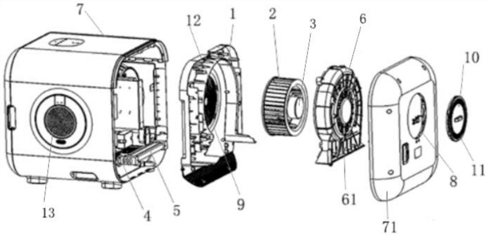
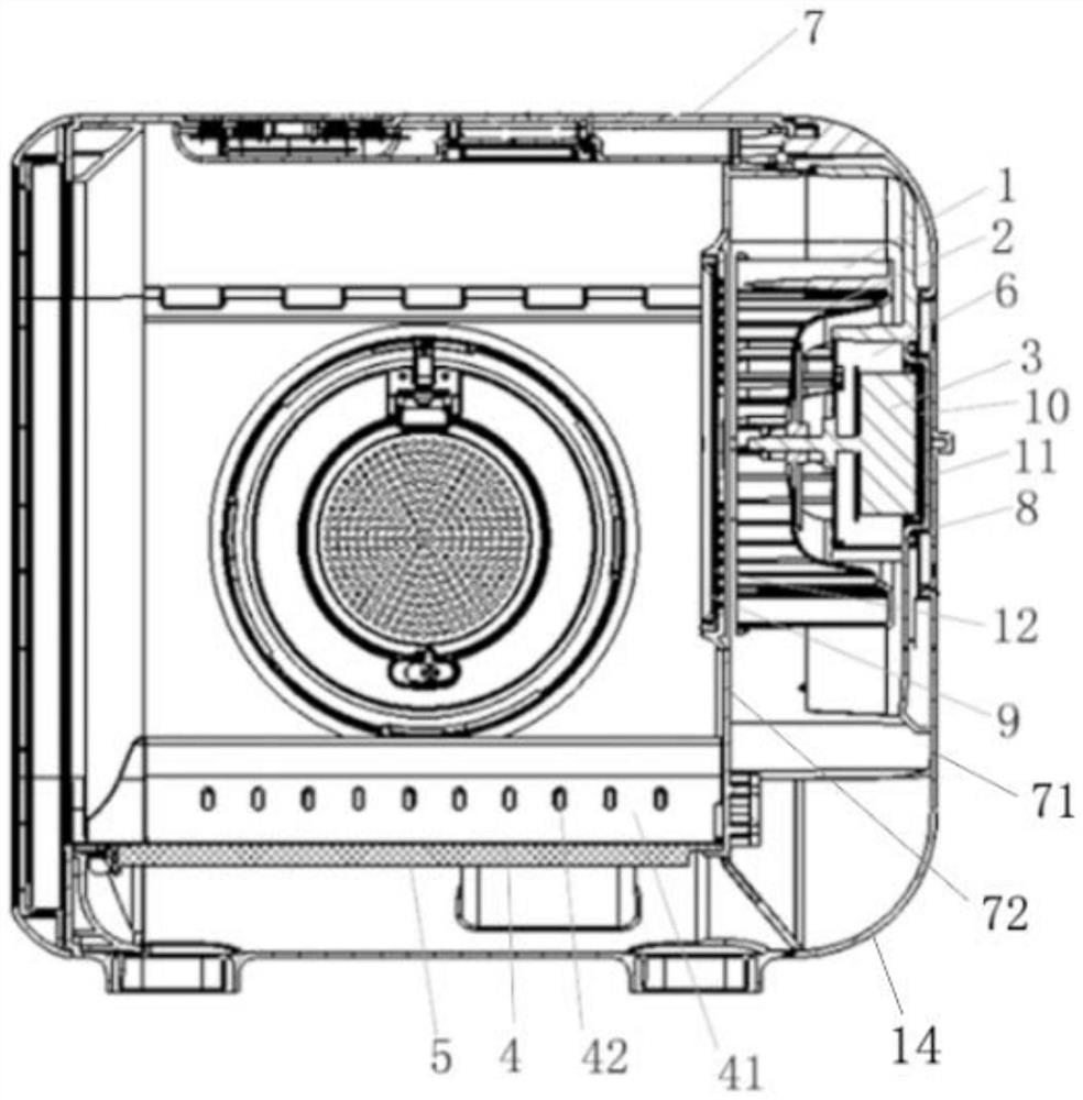
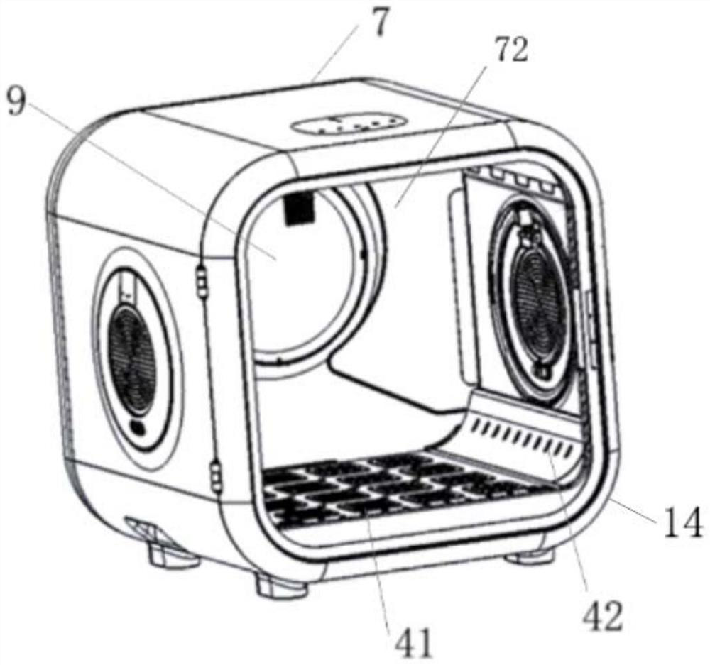
A dryer and circulating air technology, applied in cleaning devices, applications, animal husbandry, etc., can solve the problems of affecting the comfort of pets in the box, low drying efficiency, poor drying effect, etc., and achieve better drying effect. Good, reasonable air duct design, to avoid the effect of uneven hot and cold air

Pending Publication Date: 2020-11-27
SHENZHEN QIANHAI HOMERUN SMART TECH CO LTD
View PDF0 Cites 1 Cited by
  • Summary
  • Abstract
  • Description
  • Claims
  • Application Information

AI Technical Summary

Problems solved by technology

However, most of the existing pet dryers are simply a patchwork of wind wheels and heating components, without reasonable air duct design, resulting in poor drying effect and loud noise, which affects the comfort of pets in the box; Or set the wind wheel on the top or bottom of the pet dryer. The wind wheel is set on the top of the pet dryer, resulting in long air duct, large wind energy loss, and low drying efficiency, while the wind wheel is set on the pet dryer. There may be liquid leakage on the top, which poses a safety hazard

Method used


Image

  • Circulating air structure of dryer and dryer
  • Circulating air structure of dryer and dryer
  • Circulating air structure of dryer and dryer

Examples


Embodiment Construction

[0026] Orientation terms such as up, down, left, right, front, back, front, back, top, and bottom that are mentioned or may be mentioned in this specification are defined relative to their structures, and they are relative concepts. Therefore, it is possible to make corresponding changes according to its different positions and different usage states. Accordingly, these or other directional terms should not be construed as limiting terms.

[0027] The implementations described in the following exemplary examples do not represent all implementations consistent with the present disclosure. Rather, they are merely examples of approaches consistent with aspects of the disclosure as recited in the appended claims.

[0028] The terminology used in the present disclosure is for the purpose of describing particular embodiments only, and is not intended to limit the present disclosure. As used in this disclosure and the appended claims, the singular forms "a", "the", and "the" are in...


PUM


Abstract

The invention discloses a circulating air structure of a dryer and the dryer. The circulating air structure of the dryer comprises a wind wheel shell, a wind wheel and a motor, wherein the wind wheelis arranged in the wind wheel shell, a spiral air duct is formed in a gap between the wind wheel and the wind wheel shell, the wind wheel is connected with a power output shaft of the motor, and an air outlet of the spiral air duct is in butt joint with the interior of the dryer. According to the circulating air structure of the dryer, the air duct is reasonable in design, low in wind energy lossand high in drying efficiency, internal and external ventilation of the dryer can be achieved only through one wind wheel, air in the dryer can be cooled and heated more evenly, noise sources are effectively reduced, and the production cost is reduced. The invention further discloses the dryer comprising the circulating air structure of the dryer.

Description

technical field [0001] The invention relates to the technical field of drying equipment, in particular to a circulating air structure of a dryer and the dryer. Background technique [0002] The pet drying box is a kind of equipment for drying pet hair after pet bathing and grooming. However, most of the existing pet dryers are simply a patchwork of wind wheels and heating components, without reasonable air duct design, resulting in poor drying effect and loud noise, which affects the comfort of pets in the box; Or set the wind wheel on the top or bottom of the pet dryer. The wind wheel is set on the top of the pet dryer, resulting in long air duct, large wind energy loss, and low drying efficiency, while the wind wheel is set on the pet dryer. There may be liquid leakage at the top, which poses a safety hazard. Contents of the invention [0003] Based on this, one of the objectives of the present invention is to provide a circulating air structure for a dryer, which has ...

Claims


Application Information

Patent Timeline
Patent Type & Authority Applications(China)
IPC IPC(8): A01K13/00
CPCA01K13/001
Inventor 刘坤
Owner SHENZHEN QIANHAI HOMERUN SMART TECH CO LTD
Why Eureka
Try Eureka