Ultrasonic atomization core and ultrasonic atomizer

An ultrasonic wave and atomizing core technology, applied in the direction of tobacco, etc., can solve problems such as easy dry burning, affect the taste of smoke, and unsatisfactory oil guiding effect, and achieve the effect of improving the purity of smoke

Active Publication Date: 2020-11-27
CHINA TOBACCO HUNAN INDAL CORP
View PDF5 Cites 0 Cited by
  • Summary
  • Abstract
  • Description
  • Claims
  • Application Information

AI Technical Summary

Problems solved by technology

[0002] like figure 1 As shown, the airflow inlet A and the airflow outlet B of the atomization chamber where the existing ultrasonic atomizing sheet is placed vertically are arranged parallel to the ultrasonic atomizing sheet C, so that the airflow passes through the surface of the oil-conducting cotton E, so it is easy to displace the oil-conducting cotton The e-liquid particles on the surface are taken out of the atomization chamber D together, and finally inhaled by the user, affecting the taste of the vape
[0003] In addition, Chinese patent 2016208984658 discloses an ultrasonic electronic cigarette atomizer. The ultrasonic atomizing sheet is vertically placed in the electronic cigarette casing, the oil guide cotton is placed in the same direction as the ultrasonic atomizing sheet, and the oil tank is set at the bottom. In this way, the oil The e-liquid in the warehouse needs to be transmitted to the atomization surface of the ultrasonic atomizer through the oil guide rod, oil storage cotton, and oil-conducting cotton. The transportation process of the oil storage cotton, so the oil guiding effect is not very ideal, and it is prone to dry burning

Method used


Image

  • Ultrasonic atomization core and ultrasonic atomizer
  • Ultrasonic atomization core and ultrasonic atomizer
  • Ultrasonic atomization core and ultrasonic atomizer

Examples


Embodiment 1

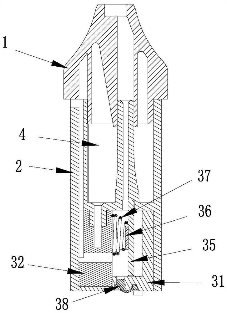
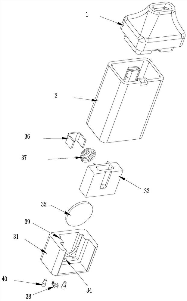
[0042] Such as figure 2 - Figure 10 As shown, an embodiment of the electronic cigarette ultrasonic atomizer of the present invention includes a suction nozzle 1, an oil tank body 2, and an atomizing core 3. The suction nozzle 1 and the oil tank body 2 are connected to each other, and the connection between the suction nozzle 1 and the oil tank body 2 Annular oil tank 4 is set between.

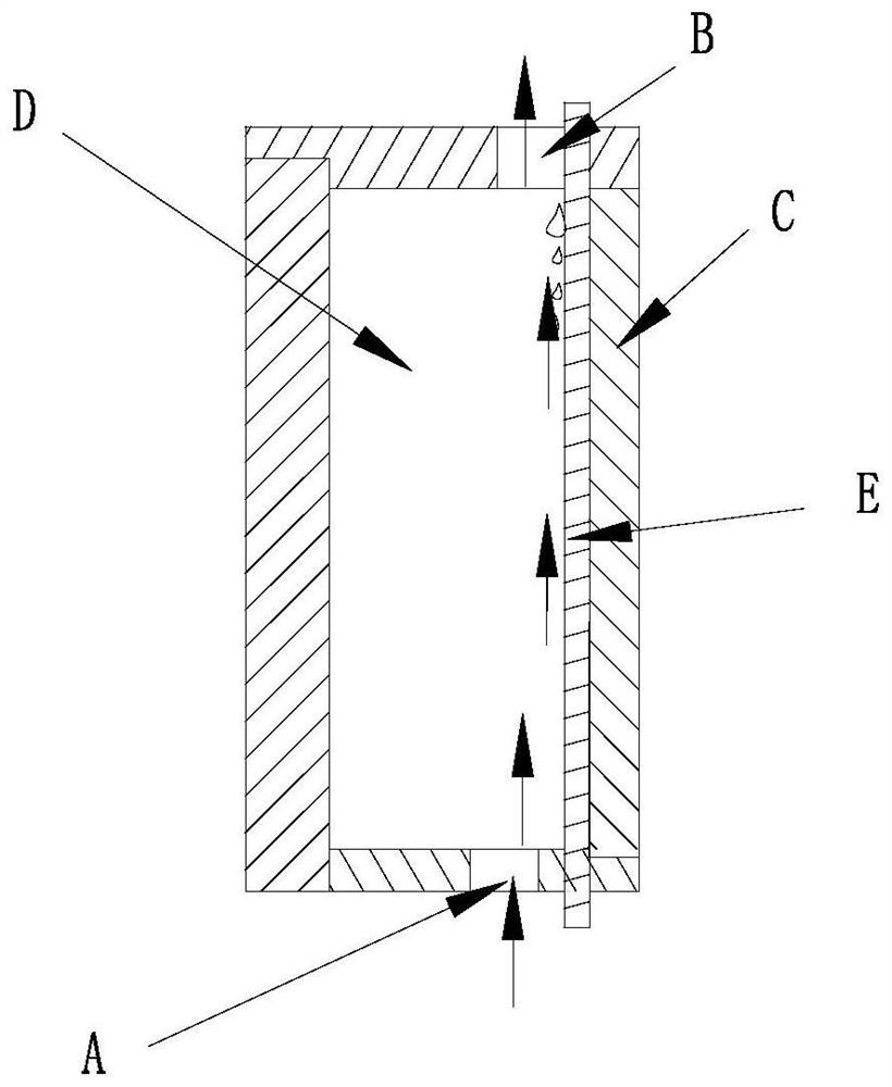
[0043] The bottom of the oil tank 4 is provided with an oil outlet section 23 communicating with the oil tank, and an oil outlet 24 is arranged in the oil outlet section 23 . An air inlet 21 is set on the outer wall of the oil tank body 2, an air inlet 22 is set between the outer wall of the oil tank body and the outer wall of the oil tank, and an air outlet 25 connected with the suction nozzle 1 is arranged in the middle of the oil tank body 2, and the air outlet 25 The bottom of the air outlet 251 is set.

[0044]The atomizing core 3 is inserted into the lower part of the oil tank body 2...


PUM


Abstract

The invention discloses an ultrasonic atomization core and an ultrasonic atomizer. An ultrasonic atomization sheet is vertically arranged on an atomization seat, an atomization cavity is formed in theatomization surface side of the ultrasaonic atomization sheet, an air inlet and an air outlet are formed in the atomization cavity, an atomization surface of the ultrasonic atomization sheet is in contact with a middle part of the oil guide cotton to form an atomization area, the air inlet is perpendicular to the ultrasonic atomization piece and located below an atomization area of the ultrasonicatomization piece, the air outlet is parallel to the ultrasonic atomization piece and located above the atomization area, and when airflow passes through the atomization cavity, a smoke flowing pathin the atomization cavity is in a peak shape so that the interior of the atomization cavity is divided into an inert area, a flowing area and a rapid area according to the smoke flowing speed. An oilstorage groove is formed in the atomization base, an oil guide cotton penetrating groove is formed between the oil storage groove and the atomization cavity, a cotton pressing spring for pressing themiddle of the oil guide cotton against the middle section of the atomization surface of the ultrasonic atomization piece to form the atomization area is arranged in the atomization cavity, and two ends of the oil guide cotton extend into the oil storage groove through the oil guide cotton penetrating groove.

Description

technical field [0001] The invention relates to an electronic cigarette set, in particular to an ultrasonic atomizing core and an ultrasonic atomizer. Background technique [0002] Such as figure 1 As shown, the airflow inlet A and the airflow outlet B of the atomization chamber where the existing ultrasonic atomizing sheet is placed vertically are arranged parallel to the ultrasonic atomizing sheet C, so that the airflow passes through the surface of the oil-conducting cotton E, so it is easy to displace the oil-conducting cotton The e-liquid particles on the surface are taken out of the atomization chamber D together, and finally inhaled by the user, affecting the taste of the vape. [0003] In addition, Chinese patent 2016208984658 discloses an ultrasonic electronic cigarette atomizer. The ultrasonic atomizing sheet is vertically placed in the electronic cigarette casing, the oil guide cotton is placed in the same direction as the ultrasonic atomizing sheet, and the oil ...

Claims


Application Information

Patent Timeline
Patent Type & Authority Applications(China)
IPC IPC(8): A24F40/40A24F40/44A24F40/48A24F40/42A24F40/05
Inventor 刘建福钟科军郭小义黄炜尹新强易建华周永权
Owner CHINA TOBACCO HUNAN INDAL CORP
Why Eureka
Try Eureka